Contents: Ignition timing angle ⇩ Adjusting the ignition timing ⇩ Fuel supply system ⇩ Control unit input signals ⇩ Output signals of the control unit ⇩ Injectors ⇩ Coolant temperature sensor ⇩ Throttle body ⇩ Throttle position sensor ⇩ Stepper motor ⇩ Fuel pump ⇩ Fuel pressure regulator ⇩ Relay block ⇩ Air temperature sensor ⇩ Inertia switch ⇩ Oxygen sensor ⇩ Fuel temperature sensor ⇩ Fuel vapor accumulator ⇩ Fuel vapor canister valve ⇩
Mpi - Modular Engine Management System (MEMS), controls fuel delivery and regulates ignition timing. Main functions of the system:
- Control of fuel supply and ignition timing in accordance with the engine operating mode. The control unit has short-circuit protection and can record codes of any faults that occur. Error codes are read by the Testbook tester.
- The control unit calculates the required amount of fuel based on signals from the air flow sensor (anemometer). Signals from the intake air temperature and pressure sensors are used to adjust the basic fuel consumption.
- When a fault is detected in the injection or ignition system, the control unit sets fixed parameter values that are safe for engine operation. In this case, as a rule, the engine characteristics (power) deteriorate.
- A separate diagnostic connector allows you to read fault codes without removing the control unit.
- All connectors are equipped with corrosion-resistant contacts.
- The throttle position sensor does not require adjustment during operation.
The control unit determines the ignition timing based on the signals:
- (1) crankshaft position sensor.
- (2) absolute air pressure sensor at the intake.
- (3) coolant temperature sensor.
- (4) knock sensor.
In this regard, there is no need to use centrifugal and vacuum regulators.
The ignition system uses two coils mounted at the rear of the engine.
Ignition timing angle
The engine management system provides an optimal ignition timing angle for all engine operating modes. The rotation speed and position of the crankshaft are determined by signals from the shaft position sensor.
The inductive position sensor works in tandem with the synchronizing ring on the flywheel. The synchronizing ring has 34 holes spaced 10° apart, the two missing holes determine the TDC position.
The engine load is determined by the signal from the absolute air pressure sensor. The sensor is mounted in the control unit housing. The pressure from the intake manifold is transmitted to the sensor via a hose.
Adjusting the ignition timing
Depending on the coolant temperature, the ignition timing angle is advanced or retarded relative to the installation angle to ensure minimal emissions of toxic components.
The control unit changes the advance angle based on signals from the knock sensor if the latter occurs. The sensor is installed on the block between the 2nd and 3rd cylinders. The advance angle can be adjusted for individual cylinders, i.e. where detonation occurs.
Note: at idle speed, the ignition timing angle is constantly changed to stabilize it.
Fuel supply system
The fuel supply is controlled by an electronic unit, which is installed in the engine compartment. The control unit is self-learning, i.e. it changes the fuel supply characteristics depending on engine wear. Fuel supply control has feedback on signals:
1. Idle speed controller stepper motor position sensor.
2. Oxygen sensor.
Note: After installing a new control unit, it must be configured using the Testbook tester.
Control unit input signals
- Crankshaft position sensor.
- Absolute air pressure sensor at the intake.
- Coolant temperature sensor.
- Intake air temperature sensor.
- Knock sensor.
- Oxygen sensor.
- Throttle position sensor.
- Idle switch.
- Battery voltage.
- Voltage in the primary circuit of the ignition coil.
- Diagnostic inputs.
- Grounding (power supply).
- Grounding (sensors).
- Fuel temperature sensor.
- Air conditioning switch.
Output signals of the control unit
- On the ignition coils.
- On the injectors.
- On the air conditioner relay.
- To the idle speed controller stepper motor.
- On the fuel pump relay.
- To the main relay of the injection system. Diagnostic outputs.
Injectors
The injectors are installed between the fuel and intake manifolds. Each injector has an electromagnetic valve and a spray nozzle that ensures that the fuel is broken up into small droplets.
Coolant temperature sensor
The sensor is installed in the thermostat housing and is washed by the coolant. When the temperature of the liquid changes, the resistance of the sensor changes.
The original article is located on: www.LRman.ru
Throttle body
The throttle body is installed on the intake manifold through a rubber gasket. The throttle valve is installed in the housing, driven by a cable from the accelerator pedal.
Crankcase ventilation tubes are attached to both sides of the valve. The tubes have an oil seal that prevents oil from the engine crankcase from entering the engine cylinders when there is a large vacuum behind the throttle. A position sensor and an idle speed control stepper motor are installed on the throttle valve axis.
Throttle position sensor
The position sensor is a three-terminal potentiometer. 5 V power is supplied to the sensor from the control unit, and a signal proportional to the degree of throttle opening is sent back to the control unit.
Stepper motor
The stepper motor has a cam, a rod and a gear reducer. The engine linkage is in contact with the throttle lever and moves the throttle valve when the engine is idling. The stepper motor rotates 3.75 revolutions in 7.5° increments.
The throttle lever has a stop for adjusting the throttle position. The stop is used to provide a connection between the motor speed and the position of the stepper motor rod.
In the throttle body there is a bypass (bypass) air channel with an adjusting screw which allows precise adjustment of the idle speed.
Stepper motor operation is checked using the Testbook tester: when idling, the speed adjustment steps should be in the range of 20-40. If the number of steps is greater than this, the idle speed must be adjusted by turning the bypass channel adjustment screw. To prevent imbalance of the idle speed control system, perform adjustments using the Testbook tester.
Fuel pump
The electrically driven fuel pump is located in the fuel tank. Centrifugal pump, submersible type. The fuel pump delivers excess fuel so that the fuel system is always under pressure.
Fuel pressure regulator
Mechanical fuel pressure regulator controlled by vacuum in the intake manifold. The regulator is installed on the fuel manifold and maintains a constant pressure difference between the fuel and intake manifolds: when the vacuum at the intake increases by the same amount, the fuel pressure decreases. Excess fuel is returned from the regulator to the tank.
Relay block
The relay box contains the main relay, fuel pump relay, starter relay and oxygen sensor relay.
The main relay supplies power to the control unit after the ignition is turned on. The fuel pump relay is powered by the control unit and turns on the fuel pump. The starter relay receives power after the ignition switch is turned to the START position. The oxygen sensor relay is powered by the control unit and supplies voltage to the sensor heater.
Air temperature sensor
The sensor is installed on the intake manifold. The sensor signal is used to calculate the air flow.
Inertia switch
An inertia switch is installed in the fuel pump circuit and cuts off power to the pump during sudden deceleration (for example, in case of an accident). The switch is installed in the engine compartment on the bulkhead.
Caution: Before setting the switch to the operating position, check the integrity of the fuel system.
Oxygen sensor
The fuel supply control system uses a sensor signal to provide feedback control of the fuel supply, which in turn minimizes the level of toxic components released from the exhaust gases.
The sensor is installed on the exhaust manifold. The sensor signal is proportional to the oxygen content in the exhaust gases: with increasing oxygen concentration (lean mixture) the sensor signal voltage decreases.
The oxygen sensor has a heater, which ensures its greater sensitivity and faster reaching of the operating mode. The operation of the heater is controlled by the oxygen sensor relay.
Fuel temperature sensor
The sensor is installed on the fuel manifold: when the engine starts, the control unit, based on the sensor signal, changes the amount of starting fuel and the position of the throttle valve to ensure a reliable start.
Fuel vapor accumulator
The accumulator serves to temporarily "storage" fuel vapors coming from the fuel tank. The accumulated fuel from the battery goes into the engine and burns there.
The battery is cleaned by drawing air through it after the valve is activated.
Fuel vapor canister valve
The operation of the valve is controlled by an electronic unit. The valve is closed when the engine is cold and idling, which prevents the mixture from becoming too rich in this mode and extends the life of the catalytic converter.
The valve opens when the engine warms up to a temperature of 75°C and a rotation speed of 1600 rpm.
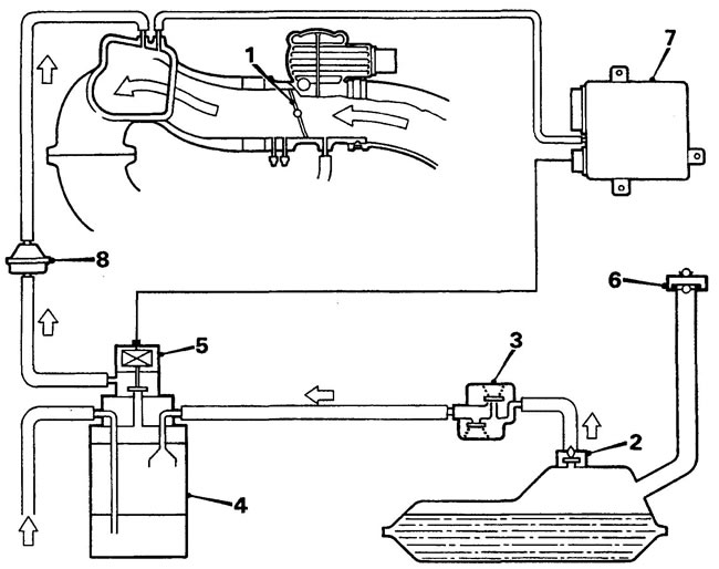
Fuel vapor recovery system: 1 - throttle valve, 2 - fuel cut-off valve, 3 - two-way valve, 4 - fuel vapor accumulator, 5 - fuel vapor accumulator valve, 6 - filler cap, 7 - control unit, 8 * check valve.
Comments on this article