Location of injection system components (old fuel vapor recovery system)
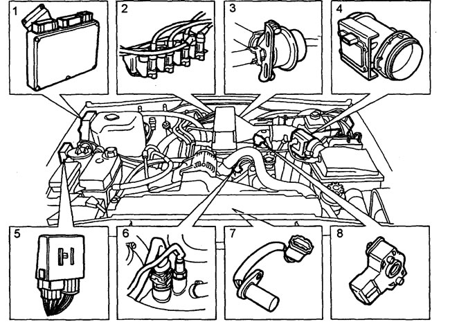
1 - engine control unit, 2 - ignition coils, 3 - fuel pressure regulator, 4 - air flow sensor, 5 - relay unit (main relay and fuel pump relay), 6 - coolant temperature sensor, 7 - camshaft position sensor, 8 - throttle position sensor.
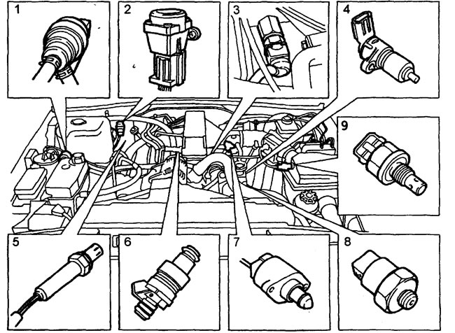
1 - fuel vapor accumulator valve, 2 - inertia switch, 3 - fuel temperature sensor, 4 - crankshaft position sensor, 5 - oxygen sensor (4 pcs.), 6 - injector, 7 - idle speed control stepper motor, 8 - knock sensor (2 pcs.), 9 - air temperature sensor.
Location of injection system components (new fuel vapor management system)
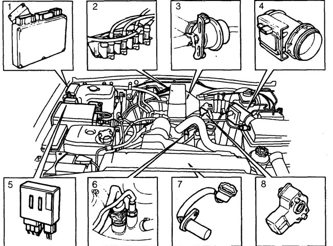
1 - engine control unit, 2 - ignition coils, 3 - fuel pressure regulator, 4 - air flow sensor, 5 - relay unit (main relay and fuel pump relay), 6 - coolant temperature sensor, 7 - camshaft position sensor, 8 - throttle position sensor.
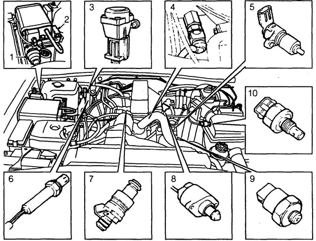
1 - vapor accumulator cleaning valve, 2 - vapor accumulator ventilation valve, 3 - inertia switch, 4 - fuel temperature sensor, 5 - crankshaft position sensor, 6 - oxygen sensor (4 pcs.), 7 - injector, 8 - idle speed control valve, 9 - knock sensor (2 pcs.), 10 - air temperature sensor.
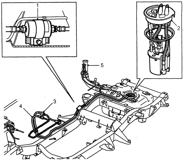
1 - fuel filter, 2 - fuel pump and fuel level sensor, 3 - fuel supply line, 4 - fuel return line, 5 - filler neck.
Note: Fuel hoses are made of reinforced nylon, do not pinch or bend the hoses.
Description
If individual components of the engine management system are faulty, the "Check Engine" indicator lights up on the instrument panel (north American version only).
The ignition system uses four dual ignition coils. A spark discharge occurs at every engine revolution (i.e. twice per working cycle). Coil #1 supplies discharge voltage to cylinders 1 and 6, coil #2 to cylinders 5 and 8, coil #3 to cylinders 4 and 7, coil #4 to cylinders 2 and 3.
Comments on this article