


Special tool
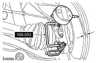
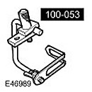 Dial indicator stand 100-053 (LRT-99-503)
 |
NOTE: If the parking brake shoes or brake discs have not been removed to gain access to other components, the bedding procedure DOES NOT NEED to be performed.
1.
CAUTION: Do not turn on the ignition when the parking brake is in service mode, as this will disengage the parking brake.
Set the parking brake to service mode.
- Turn the ignition key to position II.
- Apply and hold the parking brake.
- Set the parking brake switch to the RELEASE position and hold it in this position.
- Turn the ignition key to position 0 and remove it from the ignition switch.
- Release the foot brake.
- Release the parking brake switch.
2.
CAUTION: The brake pad wear indicator sensor is very easy to damage. Do not use a lever to remove the sensor. The operation must be performed manually.
Right side only: Disconnect the brake pad wear indicator sensor.
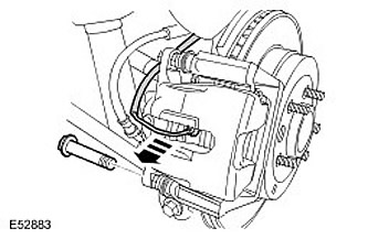
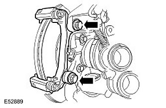
3. Remove the lower brake caliper bolt.
4. Remove the brake pads.
- Rotate the brake caliper upward.
- Remove the two clamps.
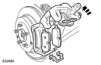
5. Remove the upper brake caliper bolt.
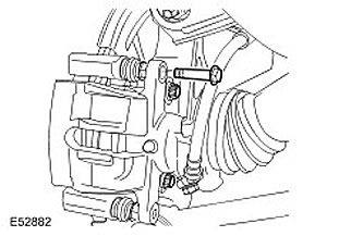
6.
CAUTION: Do not allow the brake caliper to hang by the brake hose.
Move the brake caliper housing to the side and tie it down.
7. Remove the brake caliper support bracket.
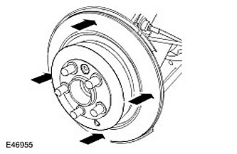
8. Measure the brake disc thickness in four places. Restore the brake disc if its thickness is less than the maximum permissible thickness or if the maximum permissible thickness deviation is exceeded. Brake disc thickness: NEW = 20 mm, maximum permissible thickness = 17 mm.
9. Using the special tool, install a dial indicator on the lower support of the brake caliper. Position the plunger of the dial indicator so that it is 5 mm from the outer edge of the brake disc.
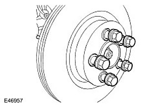
10. Tighten the wheel nuts.
- There should be spacer rings under the wheel nuts.
- Tighten the wheel nuts (tightening torque 140 Nm).
11. Rotate the brake disc one revolution to measure the brake disc runout. The brake disc runout should not exceed 0.09 mm.
12. If the brake disc runout is outside the specified limits Remove the brake disc.
13. Make sure the contact surfaces of the brake disc and wheel hub are clean.
14. Install the brake disc. Tighten the Torx head screw. (tightening torque 35 Nm).
15. Tighten the wheel nuts. There should be spacers under the wheel nuts. Tighten the wheel nuts (tightening torque 140 Nm).
16. Rotate the brake disc one revolution to measure the brake disc runout. The brake disc runout should not exceed 0.09 mm.
17. If the brake disc runout is still outside the specified limits, install a new brake disc and/or hub.
18. Remove the dial indicator and special tool.
19. Install the brake caliper support plate. Tighten the bolts. (tightening torque 115 Nm).
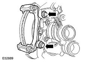
20. Install the brake caliper housing and insert the upper bolt. Tighten the bolt. (tightening torque 32 Nm).
21. Install the brake pads. Install two clamps.
22. Turn the brake caliper down. Tighten the bolt. (tightening torque 32 Nm).
23. Connect the brake pad wear indicator sensor.
24. Press the brake pedal, check the level of working fluid in the brake hydraulic reservoir and top up if necessary.
Comments on this article