Contents: Location of system components ⇩ General Provisions ⇩ Purge valve and hoses ⇩ Carbon adsorber ⇩ Diagnostic Fuel Tank Leak Test…⇩ DMTL System Operation ⇩
Location of system components
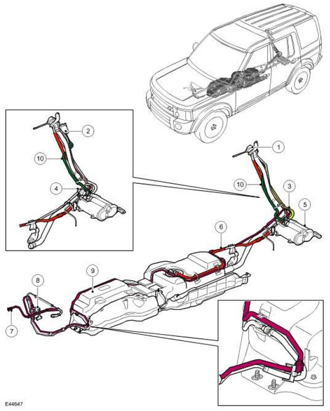
| Item name | Spare part catalog number | Description |
| 1 | - | Fuel filler neck |
| 2 | - | DMTL Pump Filter (for NAS only) |
| 3 | - | Ventilation hose connecting the fuel tank to the carbon canister |
| 4 | - | DMTL pump (for NAS only) |
| 5 | - | Carbon adsorber |
| 6 | - | Fuel tank breather hose |
| 7 | - | Blow-off hose |
| 8 | - | Purge valve |
| 9 | - | Fuel tank |
| 10 | - | Carbon adsorber ventilation hose (all models except NAS) or DMTL pump ventilation hose (only for NAS standard models). |
General Provisions
The 4.4-liter V8 EVAP system reduces the amount of hydrocarbons released into the atmosphere from the fuel tank. The system consists of a carbon canister, a purge valve, vent lines, and hoses. The vent lines are connected to the system components using quick-release connectors.
Fuel vapors are formed in the fuel tank and the higher the fuel temperature, the more so. Fuel vapors freely enter the carbon adsorber through the fuel tank ventilation system. The ventilation system includes safety flaps that prevent fuel from spilling out when the car turns over, and a liquid fuel phase separator installed inside the fuel tank and connected to the outside environment via a ventilation hose. The breather pipe removes fuel vapors to the carbon adsorber through a tee mounted on the filler neck.
In NAS standard vehicles (for North America) fuel vapors generated during refueling freely enter the carbon adsorber.
In all vehicles that do not meet the NAS standard, fuel vapors displaced from the tank during refuelling cannot enter the carbon canister, but are freely released into the atmosphere through the filler neck.
Fuel vapors entering the adsorber are absorbed by activated carbon and remain in it. Since the capacity of the carbon adsorber is limited, it must be purged. Purging is performed with the engine running, in which fuel vapors are burned.
Purge valve and hoses
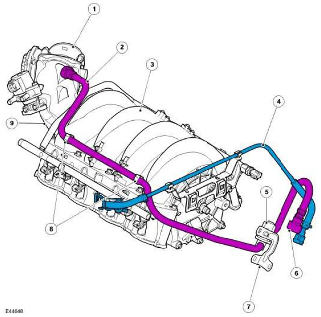
| Item name | Spare part catalog number | Description |
| 1 | - | Electronic throttle |
| 2 | - | Blow-off hose |
| 3 | - | Intake manifold |
| 4 | - | Fuel pump hose (for reference only) |
| 5 | - | Purge valve |
| 6 | - | Blow-off hose nipple |
| 7 | - | Bracket |
| 8 | - | Hose clamps |
| 9 | - | Air duct assembly |
The purge valve is located at the rear of the engine, on a bracket attached to the flywheel housing. A purge hose runs from the purge valve along the left side of the intake manifold to the air duct, which contains the throttle valve.
The purge hose, via a quick-release connector located at the rear right side of the engine, connects to the purge line, which runs above the fuel tank, next to the fuel line to the charcoal canister.
The purge hose runs from the purge valve to a connection on the inlet pipe. A quick-release connector is used to connect the hose to the pipe.
The purge valve is secured with a bolt to a bracket located on the flywheel housing. The purge valve is a normally closed solenoid valve, meaning it is closed when off. The purge valve is controlled by the engine control module (ECM) and is activated to purge the canister depending on the engine operating mode.
The valve is controlled using pulse width modulation (PWM) signals with a frequency of 10 Hz. With such a high pulse frequency, the flow of purge gas entering the intake manifold is almost continuous. The duty cycle of the valve control pulses can vary from 5 to 100%. (percentage of open state).
In the case of feedback control of fuel consumption, the ECM waits until the coolant temperature of the running engine rises above 40°C. Under these conditions, the engine runs smoothly and does not become excessively rich. (and blowing speed) increases gradually because the concentration of fuel vapor is unknown (a sharp increase in the blowdown rate may lead to excessive enrichment of the working mixture). The fuel vapor concentration is determined by the current closed-loop fuel trim that is performed to achieve the set value of the mixture composition. Once the concentration is determined, the purge rate can be quickly increased and the fuel injection volume can be adjusted in advance to compensate for the known purge volume and maintain the desired mixture composition.
In NAS vehicles, clean air enters the charcoal canister during purging through the DMTL pump air vent and pump filter, and in other vehicles through the purging hose and catcher.
The purge system in NAS standard vehicles does not have a pressure testing point. In order to pressure test the purge hose, it must be disconnected from the purge valve connector under the bottom of the vehicle, in front of the fuel tank, and a special pressure testing tool must be attached. This test determines the serviceability of the purge hose from the fuel tank to the connector on the carbon adsorber. A special pressure testing tool is attached to the hose. (for crimping).
Carbon adsorber
Carbon adsorber - except for NAS standard vehicles
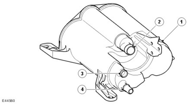
| Item name | Spare part catalog number | Description |
| 1 | - | Carbon adsorber |
| 2 | - | Air ventilation nipple of the carbon adsorber |
| 3 | - | Blow-off hose nipple |
| 4 | - | Fuel tank ventilation hose fitting on carbon canister |
Carbon Adsorber - NAS Standard Vehicles
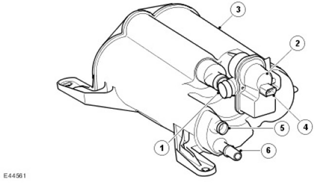
| Item name | Spare part catalog number | Description |
| 1 | - | Air ventilation nipple of the carbon adsorber (via DMTL pump) |
| 2 | - | DMTL pump |
| 3 | - | Carbon adsorber |
| 4 | - | Electrical connector |
| 5 | - | Blow-off hose nipple |
| 6 | - | Fuel tank ventilation hose fitting on carbon canister |
The carbon canister is located in the middle of the body, in front of the spare wheel. Its rear part is attached with two bolts to the spare wheel bracket. In the front part of the canister there are two projections that fit into the parking brake bracket.
In ROW standard vehicles the canister volume is 1400 cc (85.4 in.³).
In NAS standard vehicles the canister volume is 3000 cc (183 in.³).
There are three fittings on the canister to which the canister air ventilation hose, purge hose and fuel tank ventilation hose are connected. On NAS standard vehicles, the DMTL pump is connected to the canister ventilation fitting.
The adsorber contains activated charcoal. Activated charcoal is made using a special oxygen treatment technology. Oxygen treatment opens up millions of microchannels between carbon atoms, dramatically increasing the active surface area of the charcoal and its absorption capacity. After this treatment, the charcoal becomes "activated". In order for a NAS vehicle to meet the LEV 2 environmental requirements, its adsorber uses higher quality charcoal.
Diagnostic Fuel Tank Leak Test (DMTL) System
For NAS standard vehicles only
The use of the DMTL system in NAS vehicles is required by law. The DMTL periodically checks the EVAP system and fuel tank for leaks. (the check is performed with the ignition off).
The DMTL system includes all of the previously described EVAP system components plus two additional components: a pump and a filter.
The DMTL pump is connected to the adsorber vent fitting. The pump includes a heating element with a positive temperature coefficient, a normally open valve and a measuring washer. (calibrated hole). The DMTL pump is only activated when the ignition is off and is controlled by the ECM. The ECM monitors the operation of the air pump and the normal open valve.
The DMTL filter prevents the pump from drawing in dust during operation. The filter is located on the top of the fuel tank filler pipe and is connected to the pump by a hose.
DMTL System Operation
To check for leaks in the EVAP system and fuel tank, the ECM turns on the air pump and measures the current drawn by the pump. The ECM first establishes a reference current by pumping air through the orifice plate into the atmosphere. Once the reference current has been determined, the ECM closes the normally open valve, isolating the EvAp system from the outside environment. The purge valve is not energized and therefore remains closed. The pump no longer pumps air through the orifice plate, but instead supplies air to the EVAP system.
When the normally open valve closes, the load on the pump drops to zero. If the EVAP system is leaking, the pressure in the system will begin to rise, increasing the load on the pump and the current it draws. By measuring the current and the rate at which it changes, the ECM determines whether there is a leak in the EVAP system.
During normal vehicle operation, the ECM turns on a heating element in the pump. This prevents condensation from forming, which could interfere with proper current measurement.
Leaks in the system are divided into groups:
- Minor: equivalent to a hole with a diameter of 0.5 - 1.0 mm
- Significant: equivalent to a hole with a diameter of 1.0 mm or more.
- The speed of the car is zero
- The crankshaft speed is zero
- Barometric altitude (70 kPa (10.15 psi) according to the results of engine load calculations) does not exceed 3047 m above sea level.
- The outside air temperature ranges from 0-40°C.
- The saturation coefficient of the carbon adsorber does not exceed the value of 2 (the value of the saturation coefficient of fuel vapors can vary from -1 to +30). In this case, -1 corresponds to the complete absence of fuel vapors (0%), 0 corresponds to the stoichiometric ratio, and +30 corresponds to complete saturation (100%).
- The fuel level in the tank is from 15 to 85% of the nominal volume
- Before the engine was finally stopped, it had been running for at least 10 minutes.
- The battery voltage is within 10-15 V.
- At least 180 minutes have passed since the engine was last turned off.
- There are no registered malfunctions of the EVAP system components, engine coolant temperature measuring system, outside air temperature and fuel tank level
- The transfer case must be in high gear.
NOTE: The leak test can be performed using the T4 device. Using this device eliminates the need for the above conditions and makes it possible to check the correct operation of the system and its components.
The ECM checks for minor leaks after every 14 major leak search cycles and after refueling is detected.
After the leak test is completed, the ECM turns off the DMTL pump and opens (turns off the power) normally open valve.
If the filler cap of the tank is opened during the leak test (there is a sharp drop in the current consumed by the pump) or refueling is in progress (the fuel level increases), then the ECM stops checking.
If the test reveals a leak, the ECM sets a corresponding trouble code. If a leak is detected on two consecutive tests, the ECM illuminates the Malfunction Indicator Lamp (MIL) in the instrument cluster on the next trip.
The test duration can range from 40 to 270 seconds depending on the results obtained and the fuel level in the tank.
Comments on this article