Contents: Dismantling ⇩ Installation ⇩
Dismantling
1. Disconnect the negative battery terminal.
2. Remove the vacuum booster.
BRAKE SYSTEM, Rear brake drum, Vacuum booster - for vehicles with KV6 engine.
3. Place a rag near the fuel supply hose to prevent spilled fuel from spreading.
CAUTION: Fuel leakage is inevitable during this operation. Take safety measures to prevent fire or explosion.
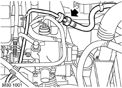
4. Slide back the rubber bushing on the fuel line connector, release the connector and disconnect the supply line from the fuel rail.
CAUTION: Always plug the fittings and holes to protect the system from dirt.
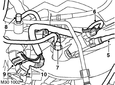
5. Loosen the clamp and disconnect the hose from the canister purge valve.
CAUTION: Always plug the fittings and holes to protect the system from dirt.
6. Disconnect the connector from the purge solenoid valve.
7. Except for North American models: Disconnect the thin vacuum hose from the canister purge valve.
8. Except for North American models: Press the shoulders and remove the vacuum hose from the idle air control valve housing.
9. Except for North American models: Disconnect the connector from the idle air control valve.
10. Except for North American models: Disconnect the connector from the throttle position sensor.
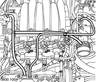
11. Press the retainer shoulders and disconnect the vacuum/purge hose from the purge valve and from the left valve cover. Loosen the clamp securing the hose to the tee and remove the hose.
12. Press the retainer shoulders and disconnect the vacuum hose/purge hose from the throttle body, from the right and left valve covers and remove the hose.
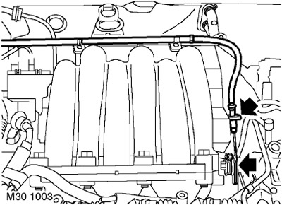
13. Except for North American models: Release the throttle control cable from the clips on the wiring harness brackets.
14. Except for North American models: Disconnect the cable housing from the bracket and disconnect the cable from the sector on the throttle body.
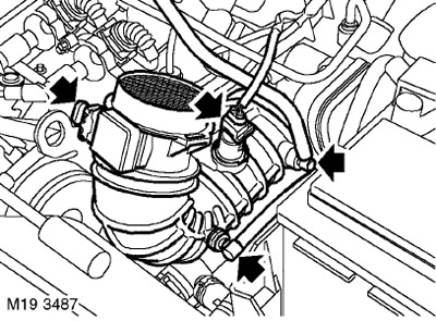
15. North American models: Disconnect the connector from the intake air temperature (IAT) and mass air flow (MAF) sensors.
16. North American models: Disconnect the crankcase ventilation hose from the air intake hose.
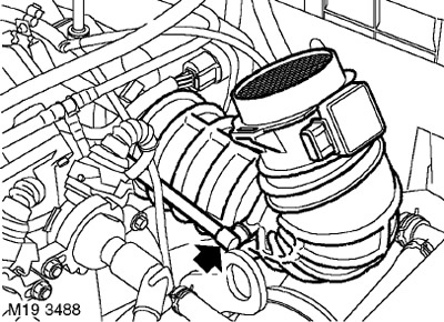
17. North American models: Disconnect the injector air supply tube from the air inlet hose.
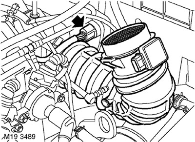
18. North American models: Disconnect the connector from the throttle body.
19. North American models: Loosen the clamp and remove the intake air hose with the MAF sensor.
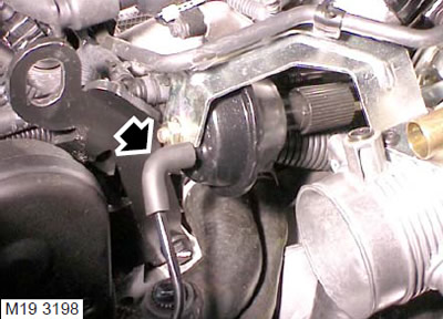
20. Disconnect the vacuum hose from the cruise control actuator.
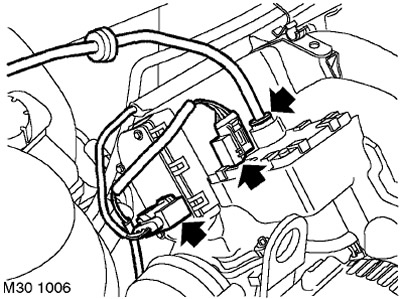
21. Press the connector shoulders and disconnect the brake booster hose from the intake manifold receiver.
22. Disconnect the connector from the intake manifold tuning system electric motors.
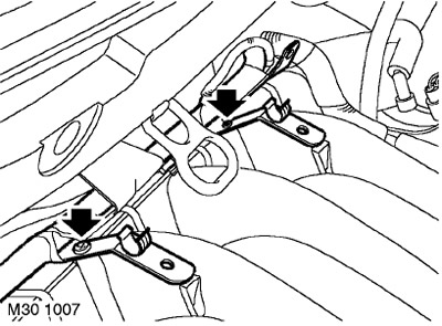
23. Unscrew the two screws securing the engine harness brackets to the intake manifold and move the harness to the side.
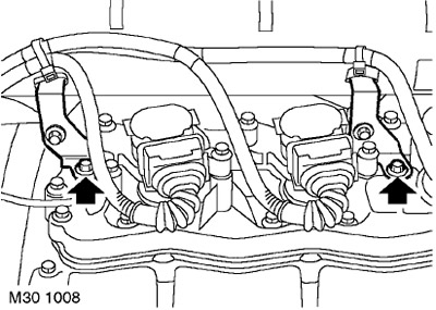
24. Unscrew the 2 bolts securing the rear receiver brackets to the right valve cover.
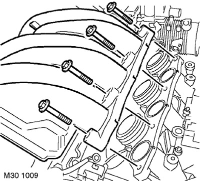
25. Unscrew the 4 bolts securing the intake receiver to the left intake manifold.
26. Release the receiver and lift it above the intake manifolds.
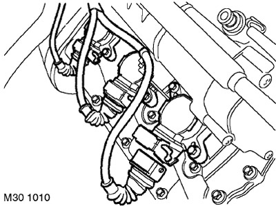
27. Release the 3 latches and disconnect the 3 connectors from the ignition coils of the right bank of cylinders.
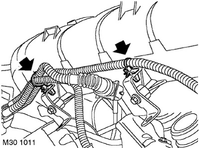
28. Release the ignition coil harnesses from the two clamps securing them to the rear brackets of the intake manifold.
29. Remove the intake receiver.
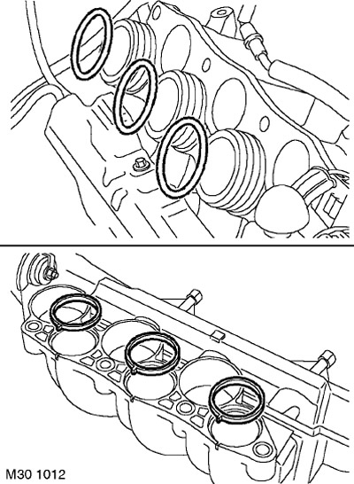
30. Remove and discard the seals from the intake manifold and the O-rings from the right intake manifold.
Installation
1. Clean the sealing surfaces of the intake manifold and intake receiver.
2. Install new sealing rings on the right intake manifold and new seals on the intake receiver.
3. Install the intake manifold, secure the right row ignition coil harness to the intake manifold brackets.
4. Connect the connectors to the ignition coils and secure the connectors with clamps.
5. Align the intake manifold with the intake manifolds, install the bolts and tighten them to 18 Nm.
6. Install the intake manifold mounting bracket to the right valve cover, screw in the bolts and tighten them to a torque of 10 Nm.
7. Install the engine harness brackets onto the intake manifold, screw in and tighten the screws.
8. Connect the connector to the intake manifold tuning system motor.
9. North American models: Connect the crankcase ventilation hose.
10. North American models: Connect the intake air temperature (IAT) and mass air flow (MAF) sensor connectors.
11. Connect the brake booster hose to the intake manifold.
12. Connect the vacuum/vent hose to the right and left valve covers and to the throttle body.
13. Connect the vacuum hose to the cruise control actuator.
14. Except for North American models: Connect the vacuum hose to the idle air control valve body.
15. Except for North American models: Connect the throttle position sensor and idle air control position sensor connectors.
16. Connect the vacuum/vent hose to the left valve cover, to the tee and to the canister purge valve.
17. Except for North American models: Connect a thin vacuum hose to the canister purge valve.
18. Connect the connector to the purge solenoid valve of the adsorber.
19. Connect the purge hose to the canister purge valve.
20. Connect the fuel line to the fuel rail, slide the rubber bushing onto the connection.
21. Remove the previously laid out rags.
22. Except for North American models: Secure the throttle control cable to the throttle lever and the cable housing to the bracket.
23. Except for North American models: Secure the throttle control cable to the clips on the wiring harness brackets.
24. Adjust the throttle control cable (if mechanical control).
FUEL SUPPLY SYSTEM OF GASOLINE ENGINE, ADJUSTMENTS, Throttle control cable - checking and adjustment: KV6 engine.
25. Remove the vacuum booster.
BRAKE SYSTEM, Rear brake drum, Vacuum booster - for vehicles with KV6 engine.
[Data taken from the website: LRman.ru]
26. Connect the negative battery terminal.
Comments on this article