Contents: Arrangement of elements ⇩ Brake pedal ⇩ Master brake cylinder and brake…⇩ Brake fluid level switch sensor ⇩ Hydraulic control unit ⇩ Service information ⇩
Arrangement of elements
NOTE: Left hand drive version shown, same for right hand drive version.
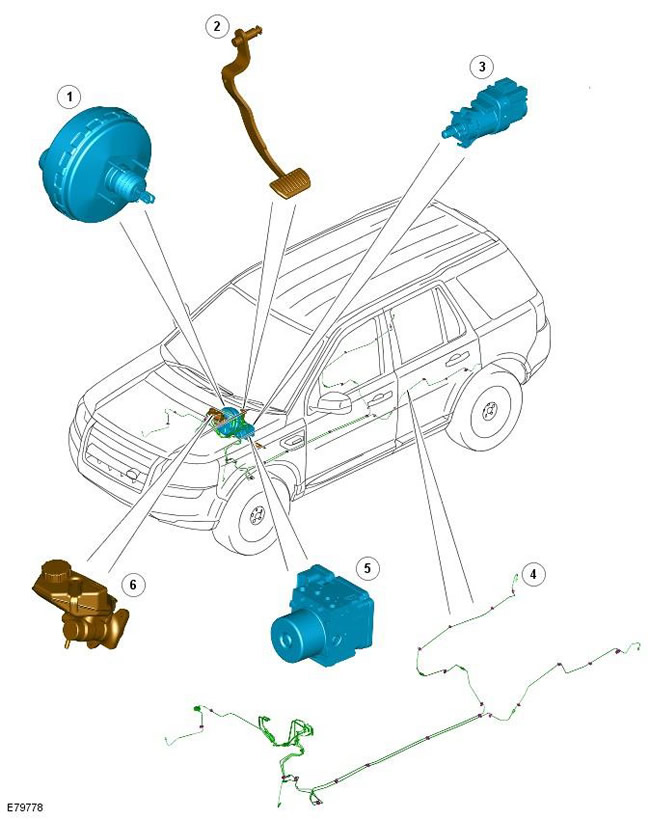
| Pos. | Spare part number | Name |
| 1 | - | Vacuum brake booster |
| 2 | - | Brake pedal |
| 3 | - | Brake light switch |
| 4 | - | Hydraulic pipelines |
| 5 | - | Hydraulic Control Unit (HCU) complete with Anti-lock Brake System (ABS) module |
| 6 | - | Master brake cylinder and brake fluid reservoir |
The hydraulic brake system is diagonally split and includes the brake pedal, master cylinder, HCU and hydraulic lines and hoses. The system also features an inactive brake booster.
Rigid brake lines supply pressure from the master cylinder to the four brake calipers via the HCU in the block with the ABS module. Flexible hoses connect the rigid brake lines to the front and rear calipers.
Brake pedal
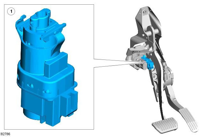
| Pos. | Spare part number | Name |
| 1 | - | Brake light switch |
The brake pedal is attached to a bracket mounted at the rear of the engine compartment bulkhead. The pedal assembly has a different design on left-hand and right-hand drive variants. It is connected to the brake booster pushrod via a pin.
The brake light switch is mounted on the brake pedal bracket and activates the vehicle's brake lights when the brake pedal is depressed. The brake light switch also serves as a source of information for the cruise control system and cancels the speed selected in the system when the brake pedal is depressed. For more information, refer to the chapter:
- Speed Control - 3.2L (310-03 Speed Control - 3.2L, Description and Operating Principle)
- Speed Control - 2.2L Diesel (310-03 Speed Control - 2.2L Diesel, Description and principle of operation)
Master brake cylinder and brake fluid reservoir
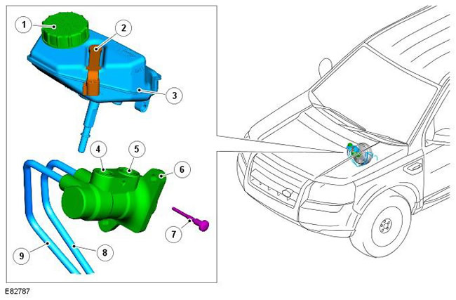
| Pos. | Spare part number | Name |
| 1 | - | Brake fluid reservoir cap |
| 2 | - | Brake fluid level switch sensor |
| 3 | - | Brake fluid reservoir |
| 4 | - | Secondary circuit inlet port |
| 5 | - | Primary circuit inlet port |
| 6 | - | Master brake cylinder |
| 7 | - | Screw |
| 8 | - | Primary circuit outlet port |
| 9 | - | Secondary circuit outlet port |
The brake master cylinder is mounted to the front of the brake booster on the driver's side of the engine compartment. The brake master cylinder is a tandem design and supplies pressure to two independent hydraulic circuits (primary and secondary). Each circuit is located between the calipers of diagonally opposite front and rear wheels, forming a fail-safe system.
The reservoir is mounted on top of the master cylinder and contains hydraulic fluid, the volume of which is sufficient for normal operation of the system and for replenishing the system to compensate for wear of the brake linings. The reservoir has an internal division for independent fluid supply to each brake circuit and prevents both the primary and secondary brake circuits from being disconnected simultaneously due to a single fluid leak. If a malfunction occurs in one hydraulic circuit, the other circuit continues to operate effectively, although the brake pedal travel and the braking distance of the car increase.
On vehicles with a manual transmission, the brake fluid reservoir also supplies hydraulic fluid for the clutch.
Brake fluid level switch sensor
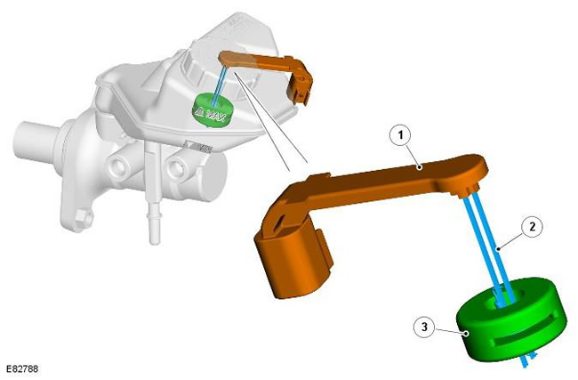
| Pos. | Spare part number | Name |
| 1 | - | Contact holder |
| 2 | - | Contact |
| 3 | - | Float |
The reservoir contains a brake fluid level sensor connected by wires to the CJB (Central Junction Box). When the fluid level in the reservoir drops to a predetermined low level, the contacts close and send a feedback signal to the CJB. The CJB then transmits a message via the medium speed CAN bus to the instrument cluster, which illuminates the red brake fluid warning lamp. For more information, refer to the chapter: Instrument Cluster (413-01 Instrument Cluster, Description and Operation).
Hydraulic control unit
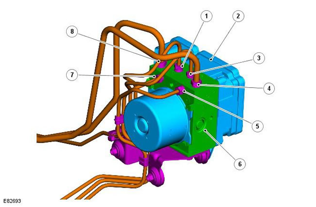
| Pos. | Spare part number | Name |
| 1 | - | Brake line to left front caliper |
| 2 | - | ABS module |
| 3 | - | Brake line to right front caliper |
| 4 | - | Primary circuit connection of the master brake cylinder |
| 5 | - | Brake line to left rear caliper |
| 6 | - | HCU |
| 7 | - | Brake line to right rear caliper |
| 8 | - | Secondary circuit connection of the master brake cylinder |
The HCU is located on the rear left side of the engine compartment and is integrated into a single unit with the ABS module. The HCU is a 4-channel unit that modulates the hydraulic pressure supply to the brakes under the control of the ABS module.
The primary and secondary outlet ports of the master cylinder are connected via 8mm brake lines to the primary and secondary circuits of the HCU. The primary circuit in the HCU has two separate outlet ports directed to the right front and left rear brake calipers. The secondary circuit in the HCU has two separate outlet ports directed to the left front and right rear brake calipers.
The HCU has three brake operating modes:
- Normal Braking/Electronic Brakeforce Distribution (EBD)
- Braking with ABS
- Active braking
Since the HCU and ABS module are a fully integrated unit, details regarding the design and operation of the HCU and ABS and their functionality, including the three braking modes, are given in this manual in the section titled "Anti-lock Brake System - Stability Assist". For more information, refer to the chapter: Anti-Lock Control - Stability Assist (206-09 Anti-Lock Control - Stability Assist, Description and Operation).
Service information
The ABS module and HCU form a single unit and must not be separated. The ABS module and HCU are supplied as a single, pre-filled unit. Once installed, the hydraulic brake system only requires normal bleeding, no bleeding under pressure is required.
NOTE: The ABS module/HCU assembly is a fragile item and should be discarded if dropped or damaged.
Comments on this article