| Pos. | spare part no | Name |
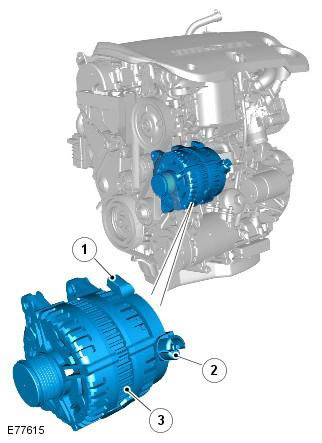
| 1 | - | LIN bus (Local Interconnect Network) |
| 2 | - | Positive battery connection |
| 3 | - | Generator |
One self-excited generator is located in front of the engine, on the left side of the cylinder block. For TD4 engines, two alternator options are available, depending on the vehicle's equipment. One alternator is rated at 90/150 A and the other at 115/180 A. The higher rated alternator is used in colder climates, on vehicles equipped with a heated windshield and an electric auxiliary heater. For more information, see chapter: Auxiliary electric heater (412-02 Additional climate control, Description and principle of operation).
Alternator pulley fitted with freewheel for improved NVH performance (noise, vibration and harshness) and extends the service life of the accessory drive belt. The freewheel clutch ensures that the belt passes over the pulley without slipping, and prevents the generator from moving the belt when the crankshaft speed changes due to the high rotational inertia of the internal elements of the generator.
The generator includes the following main elements:
- stator
- Rotor
- Rectifier
- Voltage regulator
The stator consists of a flat core into which the stator wires are pressed.
The excitation winding is located on the generator rotor. The rotor is enclosed in a stator and mounted on bearings for smooth running and support, taking into account the side loads that occur due to the tension of the drive belt.
The rectifier consists of 6 semiconductor diodes placed on a heat sink. The heat sink dissipates the resulting heat generated during electrical processes. The rectifier converts the alternating current generated in the stator coils into the direct current required by the vehicle's electrical system.
The regulator ensures that a controlled alternating voltage is obtained at the output of the generator. There are two electrical terminals on the outer case of the generator. One terminal is used to supply rectified and regulated direct current from the generator through a large diameter cable to the positive terminal of the battery. The second terminal provides a LIN bus connection between the controller and the ECM.
Regulator communicates via LIN bus with ECM, ECM also communicates via high speed CAN bus with CJB (central electrical box). The CJB contains software tables that form a mathematical model of the electrolyte temperature, and constantly receives information from the ECM about the actual battery voltage. Based on the information received, the CJB sends a predicted output voltage to the PCM over the high-speed CAN bus that is required from the regulator to efficiently charge the battery. The ECM then sends an appropriate message to the regulator on the LIN bus to reach the output voltage that is defined in the CJB. This control cycle is repeated in the presence of a closed loop.
The LIN bus is also used to communicate mechanical and wiring or connector fault information from the alternator to the ECM. A DTC is generated and stored in the ECM and, if necessary, after a short delay, the charging warning light on the instrument panel will come on.
During engine start, the charging warning light on the instrument panel comes on when the ignition is activated and goes out when the engine starts and the ECM detects that the alternator output voltage is present.
Vehicles equipped with the system «Stop/Start» - starting from MY 2010
Due to additional loads on vehicles with «Stop/Start» a 180 amp alternator is used. For more information, see the chapter: Starting system (303-06C Starting system - 2.2L Duratorq - Td4, Vehicles built from 03/2009, Description and function).
Comments on this article