car logo Ford
car logo Volkswagen
car logo BMW
car logo Opel
car logo Audi
car logo Toyota
car logo Peugeot
English Русский
Български
Беларускі
Український
Српски
Hrvatski
Română
Polski
Slovenský
Magyar


Main
Freelander
Discovery
Range Rover
Defender
Contacts
Articles

Description and principle of operation (Freelander 2)

 
  • Main
  • Freelander
  • Freelander 2
  • Power unit
  • Electronic control part
  • Description and principle of operation
 
        0  
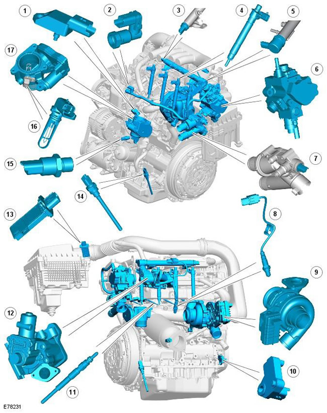
Description and principle of operation


Pos.Spare part numberName
1-Manifold Absolute Pressure (MAP) Sensor
2-Fuel temperature sensor
3-Fuel Rail Pressure Sensor
4-Nozzle (4 pcs.)
5-Pressure regulating valve
6-Fuel pump (including volume control valve)
7-Sensor (Engine Coolant Temperature) (ECT)
8-(Heated Oxygen Sensor) (HO2S)
9-Variable Nozzle Turbocharger (VNT) Controller
10-Crankshaft Position (CMP) Sensor
11-Glow plugs (4 pcs.)
12-Exhaust Gas Recirculation (EGR) Valve
13-Sensor (Mass Air Flow) (MAF)/ (Intake Air Temperature) (IAT)
14-Oil level and temperature sensor (only in vehicles with diesel particulate filter (DPF))
15-Sensor (Engine Oil Pressure) (EOP)
16-IAT sensor
17-Electronic throttle


Description and principle of operation


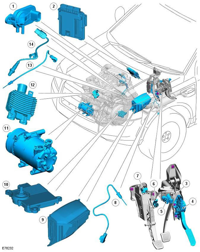
NOTE: Left hand drive (LH) shown, right hand drive (RH) similar.


Pos.Spare part numberName
1-Differential pressure sensor (only vehicles with DPF)
2-(engine control module) (ECM)
3-Brake light switch
4-Sensor (Accelerator Pedal Position) (APP)
5-Speed control system lock switch
6-Starter lock switch
7-Clutch switch
8-Lower exhaust gas temperature sensor (only vehicles with DPF)
9-(battery junction box) (BJB)
10-transmission control module - (TCM) (automatic transmission models only)
11-Air conditioning (A/C) compressor
12-Cooling Fan Control Module
13-Upper temperature sensor (only vehicles with DPF)
14-Heated oxygen sensor

The TD4 diesel engine has an Electronic Diesel Control (EDC) system. The system is controlled by the ECM module, which monitors, adapts and precisely controls fuel injection. The ECM uses input signals from various sensors and precisely controls the actuators to ensure optimum dynamic performance under all driving conditions.

The ECM controls fuel delivery to all four cylinders via a common rail fuel injection system. The common rail system uses a fuel rail to collect high-pressure fuel and feed four electronically controlled injectors. The fuel rail is located close to the injectors, which helps maintain full system pressure at each injector at all times.

The ECM uses a drive-by-wire approach to control acceleration. The command is sent from the accelerator pedal to the ECM by two potentiometers located in the throttle position sensor. The ECM uses the two signals to determine the position, rate of movement, and direction of movement of the pedal. The ECM then uses this data, along with other engine information from other sensors, to achieve optimal engine response.


ECM processes the following incoming information:

[Original article on the web portal LRman.ru]
  • CMP (CKP)
  • Temperature and air pressure in the manifold
  • Engine coolant temperature
  • Oil temperature
  • Air flow and intake temperature
  • Fuel temperature

The ECM control output signals are sent to the following sensors and actuators:
  • Fuel injectors (4 pcs.)
  • Cooling Fan Control Module
  • Electronic throttle valve
  • Turbocharger with electronically controlled vanes
  • Disabling ports
  • Fuel pressure control valve
  • Fuel volume control valve
  • EGR
  • Glow plugs (4 pcs.)


This article is available at russian, bulgarian, belarusian, ukrainian, serbian, croatian, romanian, polish, slovak, hungarian
Article review: Roman Mitrofanov


Previous article
Specification of electronic controls

Current article
Description and principle of operation

Next articles
Control scheme
Inspection and verification
Table of signs of malfunction
DTC Trouble Code Index
Camshaft Position Sensor (CMP)
Crankshaft position sensor (CPS)
Engine Coolant Temperature (ECT) Sensor
Manifold Absolute Pressure (MAP) Sensor


Similar articles from Land Rover repair manuals:
• The principle of operation of the system Discovery 3 (2004-2009)
• Operation of the electronic control system Discovery 1 (1989-1998)
• Audio system — description and principle of operation Defender 2007+ (2007-2016)

Comments on this article


No comments yet


How much will 30 + 23 =


Freelander 2 
  • General information
  • Using the manual
  • Repair technique
  • Precautionary measures
  • Road test
  • Fault codes
  • Identification codes
  • Jacking and lifting
  • Maintenance - Diesel
  • Maintenance - petrol
  • Chassis
  • Suspension
  • Front suspension
  • Rear suspension
  • Wheels and tires
  • Terrain response
  • Transmission system
  • Cardan shaft
  • Rear drive axle
  • Rear axle shafts
  • Front axle shafts
  • Brake system
  • Parking brake
  • Hydraulic brake
  • Brake booster
  • Anti-lock braking system
  • Exchange rate stability
  • Steering
  • Steering column
  • Power unit
  • Engine device
  • Engine repair
  • Description of the cooling system
  • Cooling system repair
  • Fuel supply
  • Drive units
  • Launch system
  • Ignition system
  • Exhaust toxicity
  • Air filtration
  • Fuel vapor control
  • Electronic control part
  • Automatic gearbox
  • Gearbox cooling
  • Automatic transmission controls
  • Mechanical transmission
  • Transfer case
  • Exhaust system
  • Fuel tank and lines
  • Speed control
  • Electrical equipment
  • Climate control system
  • Climate control
  • Additional climate control
  • Instrument panel
  • Sound signal
  • Information and messages
  • Assistance with parking
  • Battery and alternator
  • Information and entertainment
  • Outdoor Lighting
  • Interior lighting
  • Communication network
  • Wiring harnesses
  • Anti-theft system
  • Multifunctional modules
  • Body and coating
  • Body front panels
  • Lockable body parts
  • Interior trim
  • Rear view mirrors
  • Car seats
  • Glass, frames and mechanisms
  • Instrument panel and console
  • Handles, locks, latches
  • Windshield wipers and washers
  • Sunroof
  • Bumpers
  • Seat belt system
  • Restraint system
  • Body repairs
  • Front end repairs
  • Roof element repairs
  • Side panel repairs
  • Tailgate repairs
  • Subframe and mounts

Freelander 1 
  • General information
  • Using the manual
  • Precautionary measures
  • Technique
  • Specifications
  • Connection tightening torques
  • Maintenance
  • Power unit
  • Diesel engine Td4
  • Petrol engine K1.8
  • Piston group K1.8
  • KV6 petrol engine
  • Piston group KV6
  • Decreased toxicity
  • Motor control EDC
  • Engine management MEMS
  • Motor control Siemens
  • Fuel supply diesel Td4
  • Fuel supply for K1.8 engine
  • Fuel supply of KV6 engine
  • Cooling diesel Td4
  • Engine cooling K1.8
  • Engine cooling KV6
  • Exhaust system Td4
  • Exhaust system K1.8
  • Exhaust system KV6
  • Clutch
  • Mechanical transmission
  • Transfer case
  • Automatic gearbox
  • Chassis
  • Drive shafts
  • Rear axle and final drive
  • Steering
  • Front suspension
  • Rear suspension
  • Brake system
  • Body and coating
  • Passive safety
  • Doors, locks and glass
  • Exterior body parts
  • Interior trim details
  • Seats
  • Roof hatch
  • Roof
  • Body geometry
  • Body parts repair
  • Sealing and corrosion
  • Electrical equipment
  • Heating and ventilation
  • Air conditioning
  • Windshield wipers and washers
  • Starting engine and charging
  • Lighting and headlights
  • Control modules
  • Safety system
  • Window management
  • Entertainment systems
  • Wiring harnesses
  • Governing bodies
  • Devices


LRman.ru © 2013-2026 | Mobile version | Free Lander | Discovery | Range Rover | Defender | Contacts | | Sitemap |
Car repair and service instructions Land Rover: Freelander, Discovery, Range Rover, Defender
We use cookies to make pages load faster and provide a more user-friendly experience 🍪