Special tool
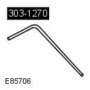 303-1270 Timing Pin, Crankshaft 303-1270 Timing Pin, Crankshaft |  303-1328 Timing Plate, Balance Shafts 303-1328 Timing Plate, Balance Shafts |
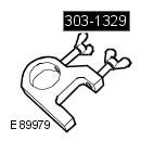 303-1329 Locking Tool, Balance Shafts 303-1329 Locking Tool, Balance Shafts | 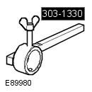 303-1330 Backlash Lever, Balance Shafts 303-1330 Backlash Lever, Balance Shafts |
1.
NOTE: The clearance can only be adjusted between the crankshaft and balance shaft assemblies. Incorrect balance shaft clearance will require replacement of the balance shaft assembly.
2.
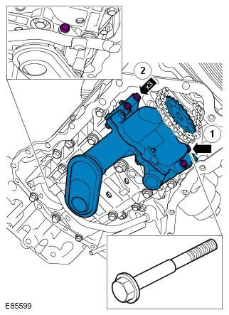
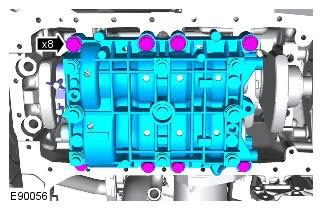
CAUTION: Note the installation location of the elements before removal.
NOTE: The shoulder bolt in position 1 secures the oil pump.
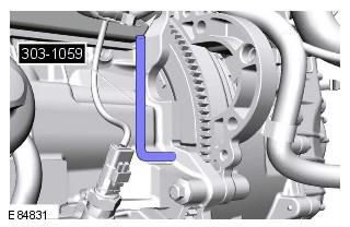
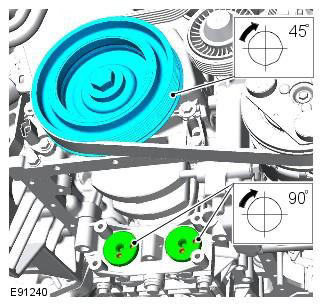
3. Turn the crankshaft and install the injection timing tool. Special tool: 303-1270
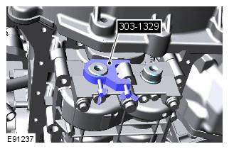
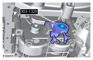
4. Lock the balance shafts. Special tool: 303-1329
5. Refer to the Engine Specifications section for balance shaft data. Refer to procedure: Specifications (303-01, Specifications).
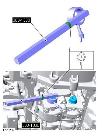
6. Measure the clearance between the balance shafts. Special tool: 303-1330
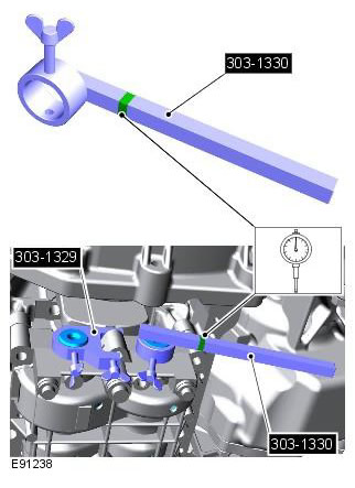
7. Install the control measuring device with a scale to the measuring point on the special tool.
8. If the clearance is out of tolerance, replace the balance shaft assembly.
9. If the balance shaft assembly needs to be replaced, go to step 17.
10. Remove the balance shaft lock. Special tool: 303-1329

11. Remove the injection timing tool. Special tool: 303-1270

12. Measure the clearance between the balance shaft and the crankshaft. Special tool: 303-1330
13. Install the control measuring device with a scale to the measuring point on the special tool.
14. Turn the crankshaft in the direction of normal rotation, measure and record the clearance of each quarter rotation of the balance shafts until 8 readings are taken and the crankshaft completes 1 complete revolution.
15. Calculate the average clearance.
16. If the gap is out of tolerance, go to step 22.
17. If a new balance shaft assembly is required.
Clean mating surfaces and remove rust and foreign material from them. Make sure the dowel pins are installed correctly.
NOTE: Install this item in the position noted when removed.

18. Remove the balance shaft assembly.
19. Select and install the largest shims available.
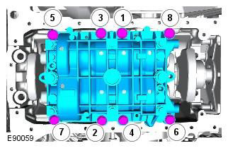
20. Install the new balance shaft assembly, tighten the bolts evenly in 2 stages in the sequence shown. Tightening torque: Stage 1: 5 Nm. Stage 2: 22 Nm
21. Repeat the clearance check.
22. Turn the crankshaft and install the injection timing tool. Special tool: 303-1270

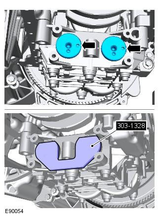
23. Install the balance shaft timing tool. Special tool: 303-1328
24. Install the balance shaft lock. Special tool: 303-1329
25. Remove the balance shaft assembly.
CAUTION: Note the installation location of the elements before removal.
26. Remove 2 shims.
Make sure that the elements are installed in the original position marked during removal. Extreme cleanliness must be observed when handling these elements.
27. Select and install new shims.
Make sure that the elements are installed in the original position marked during removal. Extreme cleanliness must be observed when handling these elements.
28. Evenly, in 2 stages, tighten the bolts in the sequence shown. Tightening torque: Stage 1: 5 Nm. Stage 2: 22 Nm
CAUTION: Clean mating surfaces and remove rust and foreign material.
NOTE: Install this item in the position noted when removed.
29. Remove the synchronizing and blocking device of the balancing shaft. Special tool: 303-1329, 303-1328
30. Repeat the clearance check.
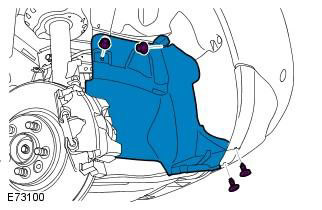
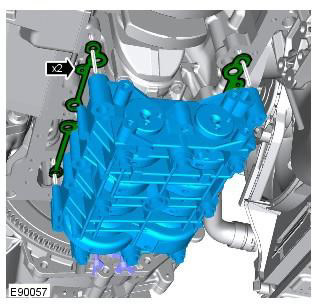
31. Install the wing mudguard extension panel.
Comments on this article