Special tool
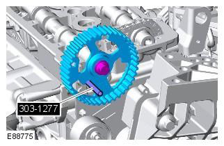
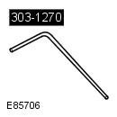 303-1270 Timing Pin, Crankshaft 303-1270 Timing Pin, Crankshaft | 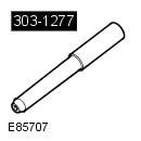 303-1277 Timing Pin, Camshaft 303-1277 Timing Pin, Camshaft |
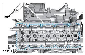
NOTE: The valve cover and cylinder head are machined as an assembly and cannot be serviced separately.
Removing
1. Remove the cover and disconnect the ground wire from the battery. Refer to procedure: Specifications (414-00 Charging system - General information, Specifications).
2. Remove the air filter assembly. Refer to Procedure: Air Filter (303-12A Intake air distribution and filtration - 3.2L NA - I6, Removal and installation).
3. Raise and support the vehicle.
WARNING: Place secure stands under the vehicle.
4. Remove the camshaft seal. Refer to Procedure: Camshaft Seal (303-01B Engine - 2.2L Duratorq - Td4, Removal and installation).
5. Remove the fuel rail. Refer to procedure: Fuel manifold (303-04B Fuel supply and controls - 2.2L Duratorq - Td4, Removal and installation).
6. Remove the fuel injectors. Refer to Procedure: Fuel Injector (303-04B Fuel supply and controls - 2.2L Duratorq - Td4, Removal and installation).
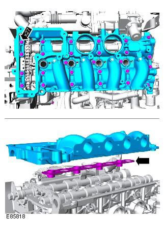
7. Remove the intake manifold. Refer to Procedure: Intake Manifold (303-01B Engine - 2.2L Duratorq - Td4, Removal and installation).
8.
NOTE: Discard the mounting clip.
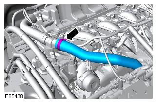
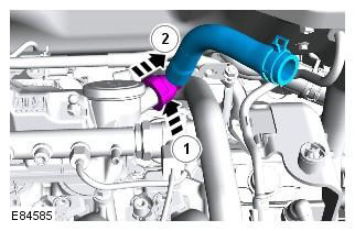
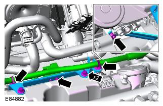
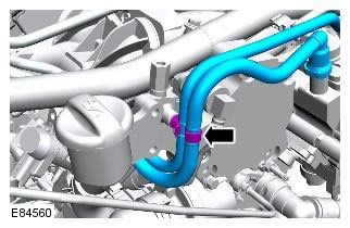
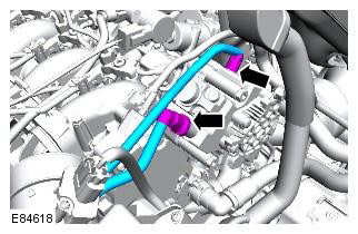
9. Remove and discard hose clamps.
10.
CAUTION: Discard slinger caps.
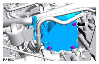
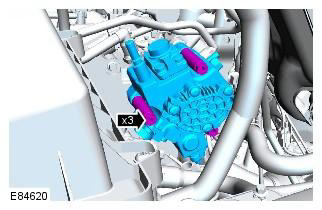
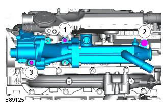
11.
CAUTION: Plug all openings.
12.
CAUTION: Discard seal.
13.
Clean the area around the element and remove foreign particles from it. Plug all openings. Use new plugs.
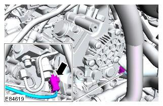
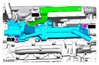
14.
CAUTION: The O-ring can be reused if it is not damaged.
NOTE: Make sure the fuel pump drive remains in place when the fuel pump is removed.
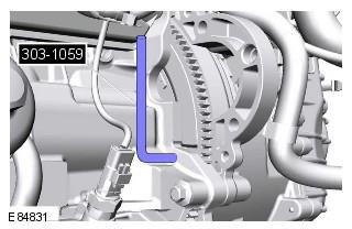
15. Remove the injection timing tool. Special tool: 303-1270
NOTE: The engine is now in the SAFE position.
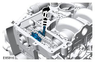
16. Rotate the crankshaft 90 degrees.
17. Move and lock the camshaft timing chain tensioner.
18.
NOTE: Discard gasket.
Installation
1. Apply a thin bead of sealant to one side. Refer to procedure: Specifications (303-01B Engine - 2.2L Duratorq - Td4, Specifications).
CAUTION: Clean mating surfaces of foreign material.
2. Temporarily install the camshaft pulley and pulley dowel pin. Special tool: 303-1277
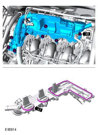
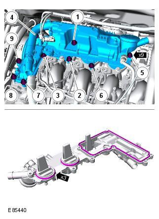
3. Install and tighten the bolts in the sequence shown in the figure.
CAUTION: Lubricate bearing surfaces with clean engine oil.
NOTE: Install a new gasket.
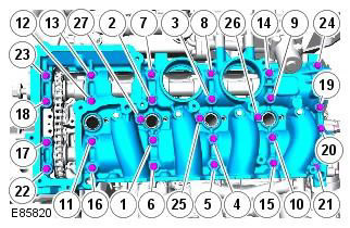
4. Tighten the bolts in the sequence shown in the figure. Tightening torque: 10 Nm
5. Loosen the chain tensioner.
6. Rotate the crankshaft and install the injection timing tool. Special tool: 303-1270
7. Remove the camshaft pulley.
8. Install the EGR cooler.
9. Install nuts, bolts and washers, but do not tighten at this stage.
10. Tighten the nuts in the sequence shown. Tightening torque: 6 Nm
11. Tighten the bolts in the order shown in the figure. Tightening torque: 10 Nm
12. Install the fuel pump. Tightening torque: 22 Nm
Extreme cleanliness must be observed when handling this element. Clean mating surfaces of foreign material. Make sure the seal is installed correctly.
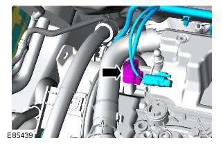
13. Connect the fuel shut-off valve electrical connector.
14. Connect the fittings of the direct and return fuel lines to the fuel pump.
WARNING: Before installing the elements, make sure that the area around the contact surfaces and connections is clean and dry.
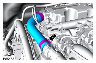
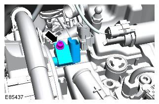
15. Install the vacuum pump. Tightening torque: 9 Nm
Clean mating surfaces of foreign material. Make sure the seal is installed correctly.
16. Attach the oil filler tube. Tightening torque: 9 Nm
17. Connect the vacuum lines to the vacuum pump. Fasten the fuel lines.
CAUTION: Clean mating surfaces of foreign material.
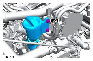
18. Install the valve cover vent oil separator. Tightening torque: 9 Nm
CAUTION: Tighten the bolts in the order shown in the figure.
NOTE: Install new seals.
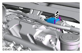
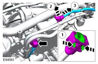
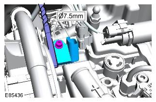
19. Insert a 7.5 mm drill bit between the cylinder head cover and the CMP sensor as shown to ensure proper alignment of the CMP sensor. Tightening torque: 4 Nm
CAUTION: Incorrect installation of the camshaft position sensor (CMP) may result in engine damage.
20. Install the cylinder head cover breather.
NOTE: Install new mounting clips.
21. Connect the CMP sensor electrical connector.
22. Connect and secure the engine vent line.
NOTE: Install a new clip.
23. Install the oxygen sensor harness bracket (HO2S). Tightening torque: 9 Nm
24. Attach the oxygen sensor harness (HO2S).
25. Install ventilation piping.
26. Install the intake manifold. Refer to Procedure: Intake Manifold (303-01B Engine - 2.2L Duratorq - Td4, Removal and installation).
27. Install the fuel injectors. Refer to Procedure: Fuel Injector (303-04B Fuel supply and controls - 2.2L Duratorq - Td4, Removal and installation).
28. Install the fuel manifold. Refer to procedure: Fuel manifold (303-04B Fuel supply and controls - 2.2L Duratorq - Td4, Removal and installation).
29. Install the camshaft seal. Refer to Procedure: Camshaft Seal (303-01B Engine - 2.2L Duratorq - Td4, Removal and installation).
30. Replace the air filter. Refer to Procedure: Air Filter (303-12A Intake air distribution and filtration - 3.2L NA - I6, Removal and installation).
31. Connect the ground wire to the battery and install the cover. Refer to procedure: Specifications (414-00 Charging system - General information, Specifications).
Comments on this article