GENERAL INFORMATION, Precautions when working with electrical equipment.
Dismantling
1. Disconnect "negative" battery terminal.
2. Remove the intake air hose.
ENGINE MANAGEMENT SYSTEM: V8 engine, REPAIR WORK, Hose connecting the air mass sensor to the throttle pipe.
3. Remove the left cover of the ignition coils.
ENGINE MANAGEMENT SYSTEM: V8 engine, REPAIR WORK, Left row ignition coil cover.
4. Remove the right cover of ignition coils.
ENGINE MANAGEMENT SYSTEM: V8 engine, REPAIR WORK, Right row ignition coil cover.
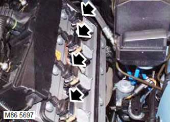
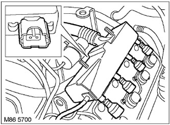
5. Disconnect the connectors from the ignition coils.
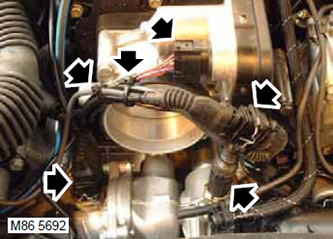
6. Disconnect connectors from throttle body, thermostat heater, camshaft position sensor (CMP) and coolant temperature sensor (ECT).
7. Cut off 2 plastic ties and release the engine harness.
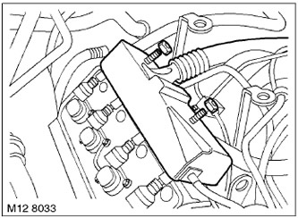
8. Disconnect the connectors from the solenoid valves of the variable valve timing system (VCC).
9. Release the VCC solenoid valve connector from the clamp.
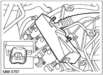
10. Disconnect the block from the fuel vapor absorber purge solenoid valve.
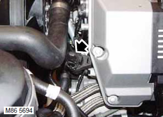
11. Disconnect the connector from the generator.
12. Release the generator harness from 4 clamps.
13. Disconnect the block from the knock sensor (KS) and camshaft position sensor (CMP).
14. Turn away 2 bolts of fastening of a plait of electroconducting of fuel atomizers to a fuel rail.
15. Release the vacuum reservoir and mounting bracket from the left stud of the fuel injector wiring harness.
16. Remove the fuel pipe and bracket from the left stud of the fuel injector wiring harness.
17. Release the generator harness from the two clamps on the brackets of the upper engine casing.
18. Disconnect the connectors from the left row injectors.

19. Disconnect the motor harness from the clamps and take it away from the valve cover.
20. Turn away 2 nuts of fastening of a motor plait to an inlet highway.
21. Disconnect the electrical connector from the SAI solenoid valve (afterburning systems).
22. Remove the SAI valve (afterburning systems) from the right stud of the injector harness.
23. Remove the washer from the fuel injector harness stud.
24. Disconnect the connector from the right knock sensor (KS).
25. Disconnect the connectors from the right row injectors.
26. Bring to the place a plait of wires of fuel atomizers.
27. Remove the receiving air receiver.
HEATING AND VENTILATION, REPAIR WORKS, Air intake box.
28. Relieve residual pressure in the fuel supply system.
V8 FUEL SUPPLY, ADJUSTMENTS AND MAINTENANCE, Relief Pressure Relief.
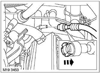
29. Disconnect the fuel supply hose from the fuel rail.
CAUTION: Always plug fittings and openings to keep dirt out of the system.
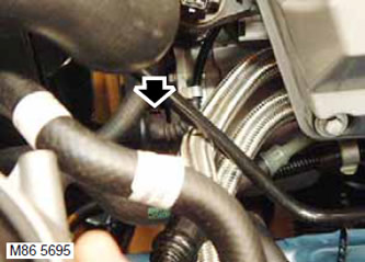
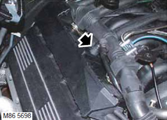
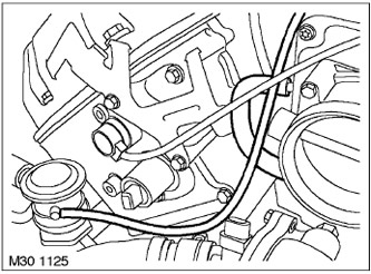
30. Loosen the clamp and disconnect the crankcase ventilation hose from the valve cover.
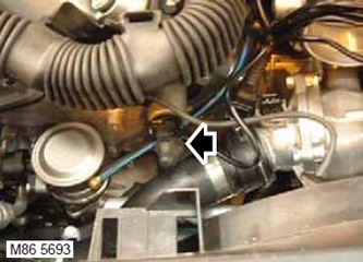
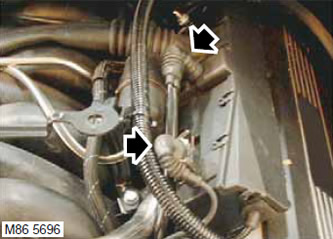
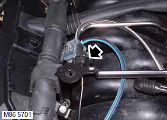
31. Turn away a collar and disconnect a vacuum hose from the electrovacuum valve of a purge of an absorber. Disconnect the vacuum tube SAI (afterburning systems).
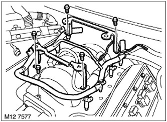
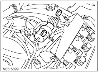
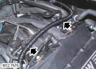
32. Turn away from an inlet collector 4 bolts of fastening of arms of the top casing of the engine.
33. Turn away a bolt of fastening of a fuel stage to an inlet collector and remove a stage with atomizers.
Assembly
1. Wipe the nozzles and recesses in the intake manifold.
2. Insert the rail injectors into the intake manifold and screw in the bolt.
3. Fit 2 new brackets to manifold and tighten 5 bolts. Tightening torque 10 Nm.
4. Install the electrovacuum valve and connect the vacuum tube.
5. Bring a vacuum tube of the vacuum brake booster.
6. Attach a vacuum hose of brake system and fix it with a collar.
7. Attach the crankcase ventilation hose to the valve cover and tighten the clamp.
8. Wipe fuel hose connectors.
9. Attach the fuel supply hose to the fuel rail.
10. Reinstall the intake air receiver.
HEATING AND VENTILATION, REPAIR WORKS, Air intake box.
11. Bring to the place a plait of wires of fuel atomizers.
12. Attach the connectors to the nozzles of the right row.
13. Connect the connector to the knock sensor (KS).
14. Install the washer on the fuel injector harness stud.
15. Install SAI valve (afterburning systems) on the right stud of the injector harness.
16. Screw on 2 nuts of fastening of a plait of fuel atomizers to an inlet highway and tighten them.
17. Connect the connector to the afterburner solenoid valve (SAI).
18. Install on the bracket and secure the engine harness with clamps.
19. Connect the connectors to the left row injectors.
20. Attach the generator harness to the two clamps on the upper engine cover.
21. Install the fuel hose with bracket on the left-hand injector harness stud.
22. Attach the vacuum reservoir with the bracket to the left-hand injector harness mounting stud.
23. Screw on 2 nuts of fastening of a plait of fuel atomizers to an inlet highway and tighten them.
24. Connect the connector to the knock sensor (KS).
25. Connect the connector to the camshaft position sensor (CMP).
26. Secure the generator wiring harness with 4 clips.
27. Connect the generator connector.
28. Connect the connector to the fuel vapor absorber purge valve.
29. Fix in the clamp the connector of the harness of the variable valve timing system (VCC).
30. Connect the connectors to the solenoid valves of the valve timing regulators (VCC).
31. Install new plastic clamps and secure the harness.
32. Connect the connector to the camshaft position sensor (CMP).
33. Connect the connector to the throttle pipe.
34. Connect the block to the coolant temperature sensor (ECT).
35. Put the connectors on the ignition coils.
36. Establish the left cover of coils of ignition.
ENGINE MANAGEMENT SYSTEM: V8 engine, REPAIR WORK, Right row ignition coil cover.
37. Establish the right cover of coils of ignition.
ENGINE MANAGEMENT SYSTEM: V8 engine, REPAIR WORK, Left row ignition coil cover.
38. Replace the intake air hose.
ENGINE MANAGEMENT SYSTEM: V8 engine, REPAIR WORK, Hose connecting the air mass sensor to the throttle pipe.
Comments on this article