Contents: Glass, frames and mechanisms ⇩ Windshield ⇩ Rear Window Components ⇩ Location of components in window…⇩ General Provisions ⇩ Input and output signals of the…⇩ Ignition switch ⇩ Window lift switches ⇩ Contacts of the switch block in the…⇩ Rear passenger door switch block…⇩ Front open door contact sensors ⇩ Permissive chains ⇩ Window lift mechanisms ⇩ Front door window lifts ⇩ Rear door window lifts ⇩ Anti-jam protection ⇩ Initialization of the electric drive…⇩ Anti-jam window contacts in driver's…⇩ Window lifter control diagram ⇩
Glass, frames and mechanisms
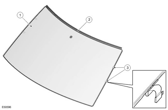
| Item name | Spare part catalog number | Description |
| 1 | - | Windshield |
| 2 | - | Edging |
| 3 | - | Windshield Heating Connectors |
Windshield
The multilayer windshield has undergone heat treatment and is hermetically sealed into the body frame using polyurethane sealant. An optical element, which is part of the rain sensor, is installed on the inner surface of the glass under heating, as well as a boss for attaching the interior mirror.
To free the glass from frost and condensation, a vertical electrically conductive mesh is mounted between its layers. In the lower part of the glass, on the inside, six horizontal heating elements are installed, which prevent the windshield wipers from freezing to the glass in frosty weather. For more information, contact Control Components (412-04 Control Components)
The windshield comes with flat electrical connectors for the heating elements that connect to a sealed terminal block. This block provides the connection between the connectors and the vehicle's electrical system.
Rear Window Components
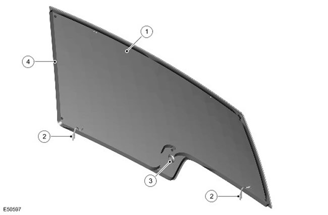
| Item name | Spare part catalog number | Description |
| 1 | - | Rear window |
| 2 | - | Rear window heating connectors |
| 3 | - | Rear window wiper motor hole |
| 4 | - | Sealant |
The tempered rear glass is hermetically sealed into the rear window frame using polyurethane sealant. The inside surface of the rear glass contains heating elements and an additional antenna for diversity reception of FM radio broadcasts. (for some configuration options). For more information, please contact Antenna (415-02 Antenna)
The heating element is connected via 2 lucar terminals, while the antenna is connected to the vehicle via a single and twin plug connector located at the top of the glass. For more information, please contact Control Components (412-04 Control Components)
Location of components in window lifters
NOTE: Left hand drive vehicle shown, component locations are similar for right hand drive vehicle.
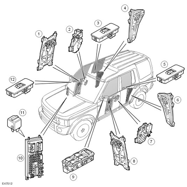
| Item name | Spare part catalog number | Description |
| 1 | - | Front passenger window lift motor |
| 2 | - | Front passenger door latch (open door contact sensor) |
| 3 | - | Right rear window lift switch |
| 4 | - | Electric motor of the window lifter of the right rear window |
| 5 | - | Left rear window lift switch |
| 6 | - | Electric motor for window lift, left rear window |
| 7 | - | Driver's door latch (open door contact sensor) |
| 8 | - | Driver's door window lift motor |
| 9 | - | Driver's door switch block |
| 10 | - | Central Junction Box (CJB) |
| 11 | - | Window lifter relay |
| 12 | - | Front passenger door window switch |
General Provisions
All four doors are equipped with electric windows. The driver's window has an adjustable 'Anti-trap' function. (anti-seize), which is combined with the one-touch switch control function. All passenger door windows are wired to the CJB via a window relay. From 2007 onwards, the one-touch switch control function will also be provided on the front passenger door.
If two different switches send conflicting commands, such as the driver's door switch and a separate door switch, power window operation will be interrupted until one or both switches are released.
Input and output signals of the system
| Input signals | Output signals |
| Ignition switch | Power window control enable signal from CJB |
| Driver's door switch block | Power supply for window lifters from CJB unit |
| Front passenger door window switch | Right and left front door window lift drives |
| Left and right rear door window switch | Right and left rear door window lift drives |
| Driver's door open contact sensor | - |
| Front passenger door open contact sensor | - |
Ignition switch
The windows can operate when the ignition key is in positions I and II, but do not operate when the engine is cranking.
T4 can be used to monitor the state of the ignition switch.
Window lift switches
Each of the three passenger doors has a window switch. The driver's door trim panel has switches for all the windows.
All window lift switches are non-locking, rocker-type, with built-in lighting that works when the side lights or headlights are on.
Driver's door window switches (and on models produced from 2007 onwards - window switches on the front passenger door) have two positions in each direction: slow up/down and one-touch up/down. Pressing the switch until it clicks a second time activates one-touch glass movement. All passenger door windows are powered by conventional electric motors that move the glass slowly up or down when the appropriate switch is pressed.
When the passenger window lifts are operated or the rear window lifts are locked using the driver's door switches, the switches send a signal to the corresponding window lift. When the lock is engaged, the rear window lifts ignore requests from the individual switches, and the LED on the lock switch in the driver's door switch block lights up.
When the switch is in the neutral position, battery voltage is supplied to both sides of the switch and the same voltage is supplied to the window lift motor. When either switch is pressed, ground is connected to the window lift motor. Pressing the switch in the opposite direction swaps the voltage and ground, causing the motor to rotate in the opposite direction.
Power to the window motors is supplied via the window relay located in the CJB. When energized, the relay supplies power to the following fuses, also located in the CJB:
- 30 (25 A)
- 17 (20 A)
- 31 (20 A)
| Fuse box | Name |
| Fuse 7 | Driver's door window lifter |
| Fuse 17 | Driver's door switch block: up/down - rear right door |
| Rear right window switch (via the lock switch) | |
| Fuse 30 | Driver's door switch block: up/down - front passenger door |
| Front passenger door switch: up/down | |
| Fuse 31 | Driver's door switch block: up/down - rear left door |
| Rear left window switch (via the lock switch) |
Contacts of the switch block in the driver's door
Connector C0081
| Contact No. | Name | Input signal/output signal |
| 1 | Lowering the front passenger window | Output signal |
| 2 | Raising the front passenger window | Output signal |
| 3 | Power from the battery - to the front passenger door window | Input signal |
| 4 | Lowering the driver's window | Output signal |
| 5 | Driver's window lift | Output signal |
| 6 | "Weight" | - |
Connector C0343
| Contact No. | Name | Input signal/output signal |
| 1 | Power supply from the battery - to the rear left door window lifter | Input signal |
| 2 | Lowering the right rear door window | Output signal |
| 3 | Raising the right rear door window | Output signal |
| 4 | Power supply from the battery - to the rear right door window lifter | Input signal |
| 5 | Lowering the left rear door window | Output signal |
| 6 | Raising the left rear door window | Output signal |
| 7 | Switch illumination | Input signal |
| 8 | "Weight" | - |
Connector C2654
| Contact No. | Name | Input signal/output signal |
| 1 | Not used | - |
| 2 | Power supply for rear right window lifter (via the lock switch) | Input signal |
| 3 | Not used | - |
| 4 | Not used | - |
| 5 | Not used | - |
| 6 | Power supply for rear left window lifter (via the lock switch) | Input signal |
| 7 | LED child lock switch status | Input signal |
| 8 | Child lock switch | Output signal |
Rear passenger door switch block contacts
Connector C0732
| Contact No. | Name | Input signal/output signal |
| 1 | Power supply for lifting from the switch block in the driver's door | Input signal |
| 2 | Power supply for glass lifting - to the window lifting mechanism | Output signal |
| 3 | Power supply for lowering from the switch block in the driver's door | Input signal |
| 4 | Not used | - |
| 5 | "Mass" of switch illumination | - |
| 6 | Power supply for switch backlight | Input signal |
| 7 | Power supply for lowering the glass - to the window lift mechanism | Output signal |
| 8 | Power supply from the switch block in the driver's door | Input signal |
The T4 device cannot be used to check the status of the window lifter switches, as they are part of the normal electrical circuit.
Front open door contact sensors
The window lift control is immediately interrupted for 40 seconds after the front door is opened. The door open contact sensors are located in the latch mechanisms of the front door locks.
To check the status of door opening sensors, you can use the T4 device.
Permissive chains
The use of enabling circuits allows the windows to be used only when the ignition key is in position I or II and for 40 seconds after the ignition is switched off. If the driver's or front passenger's door is opened within 40 seconds, the windows will not operate.
While the engine is cranking, the operation of the windows is not permitted.
Window lift mechanisms
The window lift cable mechanism is driven by a drive; each door has its own electric drive.
Front door window lifts
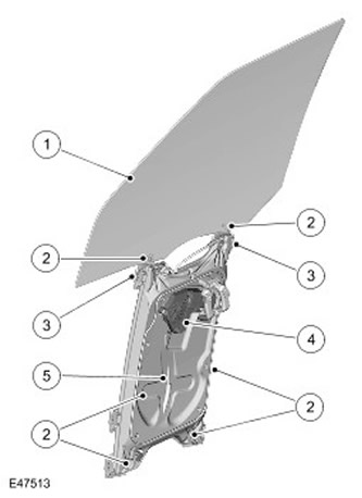
| Item name | Spare part catalog number | Description |
| 1 | - | Glass |
| 2 | - | Attachment points |
| 3 | - | Glass holder |
| 4 | - | Electric window lifter |
| 5 | - | Mounting frame |
| 6 | - | Cable |
The front power window is supplied as a single unit. Each window contains front and rear guides, an endless cable and a power drive.
The guides are secured to the door frame with four screws. The door glass is secured in two holders located in the grooves of the guides. The glass is held in damping pads in each holder and secured with screws.
Each holder is attached to a cable connected to a drum, which is driven by an electric motor. As the motor shaft rotates, the drum pulls the cable in the desired direction, raising or lowering the glass.
Rear door window lifts
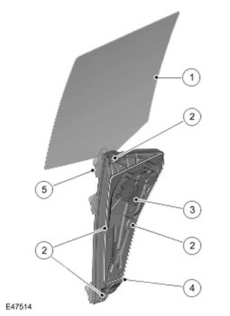
| Item name | Spare part catalog number | Description |
| 1 | - | Glass |
| 2 | - | Attachment points |
| 3 | - | Electric window lifter |
| 4 | - | Mounting frame |
| 5 | - | Glass holder |
The rear power window is supplied as a single unit. Each window contains a guide, an endless cable and a power drive.
The guide is secured to the door frame with four screws. The door glass is secured in a holder located in the guide groove. The glass is held in damping pads in the holder and secured with a screw.
The holder is attached to a cable connected to a drum, which is driven by an electric motor. When the motor rotates, the drum pulls the cable in the desired direction to raise or lower the glass.
Anti-jam protection
The driver's window anti-jam function operates both in the window lifting mode by holding the window lift switch and in the window lifting mode by pressing the switch once. If the anti-jam sensor is triggered during the window lifting, the window lift electric drive will move in the opposite direction for 0.5 seconds.
The Hall sensor, located in the driver's door window, monitors the speed of the glass and if the speed drops below a set limit (this is a sign of seizure), the power supply polarity switches and the electric drive begins to rotate in the opposite direction.
In an emergency, the safety function can be deactivated by holding the switch in the one-touch closed position.
To ensure that the one-touch control mode continues to operate after the battery is disconnected, the driver's door window lifter must be initialized.
Initialization of the electric drive in the driver's door
- Press the window switch on the driver's door until the window is completely closed, continue holding the switch for another two seconds.
- Release the window switch
- With the driver's window closed, press the switch again to the close position and hold for two seconds.
- Press the switch until the window is fully open. (in one motion).
NOTE: If the electric drive initialization was performed correctly, the driver's window should automatically close completely when the switch is pressed. (in one motion). If the window does not close automatically completely (in one motion), repeat the whole procedure.
Press the driver's door window switch once to the closed position.
Anti-jam window contacts in driver's door
Connector C0740
| Contact No. | Name | Input signal/output signal |
| 1 | Rise signal | Input signal |
| 2 | Lowering signal | Input signal |
| 3 | Powered by battery | Input signal |
| 4 | "Weight" | - |
| 5 | Not used | - |
| 6 | Enable chain | Input signal |
Window lifter control diagram
NOTE: A = Wired
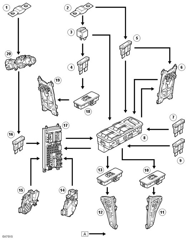
| Item name | Spare part catalog number | Description |
| 1 | - | Fuse link 11 |
| 2 | - | Fuse link 18 |
| 3 | - | Window lifter relay |
| 4 | - | Fuse 30 |
| 5 | - | Fuse 7 |
| 6 | - | Electric window lifter driver's door |
| 7 | - | Fuse 31 |
| 8 | - | Driver's door switch block |
| 9 | - | Fuse 17 |
| 10 | - | Right rear window lift switch |
| 11 | - | Electric window lifter, right rear window |
| 12 | - | Electric window lifter left rear window |
| 13 | - | Left rear window lift switch |
| 14 | - | Driver's door latch (open door contact sensor) |
| 15 | - | Front passenger door latch (open door contact sensor) |
| 16 | - | Fuse 60 |
| 17 | - | Central Junction Box (CJB) |
| 18 | - | Front passenger door window switch |
| 19 | - | Electric window lifter front passenger door |
| 20 | - | Ignition switch |
Comments on this article