Contents: Location of parts ⇩ General Provisions ⇩ Manual dimming interior mirror ⇩ Auto-dimming interior mirror ⇩ Auto-dimming interior mirror with…⇩ Automatic dimming ⇩ Universal transmitter ⇩ Exterior mirrors ⇩ Heating ⇩ Duty cycle of control signals for…⇩ Adjustment ⇩ External mirror position regulator ⇩ Recalling adjustments from memory ⇩ Outside mirror ⇩ Mirror tilt when reversing ⇩ Folding mirrors ⇩ Connector C0907 folding module…⇩ Contacts of connector C0907 of the…⇩ Control system diagram (exterior…⇩ Control system diagram (exterior…⇩
Location of parts
NOTE: Model shown is RHD (left hand drive model), LHD (right hand drive model) similar.
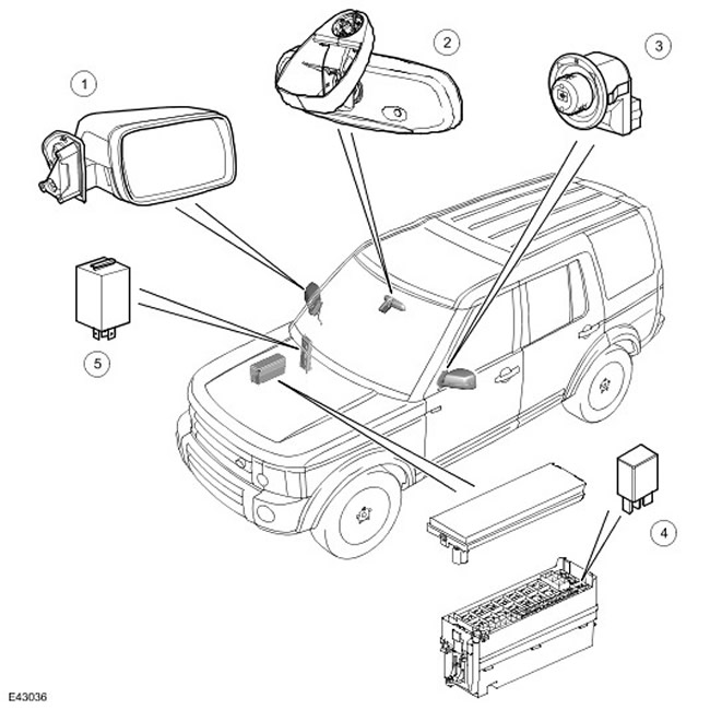
| Item name | Spare part catalog number | Description |
| 1 | - | Outside mirror |
| 2 | - | Interior mirror (the model shown is one with automatic dimming) |
| 3 | - | External mirror position regulator |
| 4 | - | Windscreen washer nozzle/external rear view mirror heater relay |
| 5 | - | Folding module |
General Provisions
The rear view mirrors include an inside mirror above the windshield and an outside mirror mounted on the panel of each front door.
Manual dimming interior mirror
Auto-dimming interior mirror
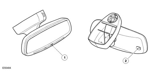
| Item name | Spare part catalog number | Description |
| 1 | Rear light sensor | |
| 2 | Front light sensor |
Auto-dimming interior mirror with integrated universal transmitter
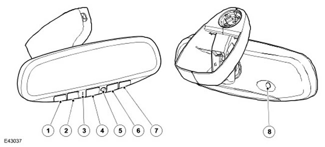
| Item name | Spare part catalog number | Description |
| 1 | - | Channel 1 button of the universal transmitter |
| 2 | - | Channel 2 button of the universal transmitter |
| 3 | - | Status indicator |
| 4 | - | Channel 3 button of the universal transmitter |
| 5 | - | Rear light sensor |
| 6 | - | Dimming On/Off Button |
| 7 | - | Dimming off button |
| 8 | - | Front light sensor |
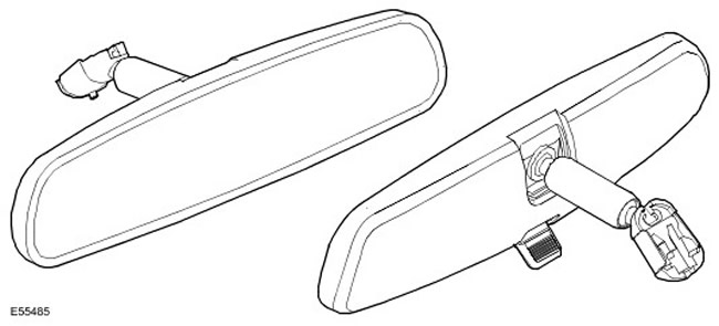
The interior rearview mirror has manual or automatic dimming. Manual dimming is achieved by moving the mirror to the dimming position using a lever on the bottom of the mirror housing. Automatic dimming is achieved by the mirror's electrochromic glass.
Depending on the configuration and market, the mirror may be equipped with a universal HomeLink® transmitter.
NOTE: HomeLink is a registered trademark of Johnson Controls Inc.
Mirrors with a universal transmitter and/or auto-dimming function are connected to the vehicle's electrical system via a connector located under the cover plate in the mirror base. Power to the universal transmitter and/or the auto-dimming interior mirror is supplied from the CJB when the ignition is switched on (in position II).CJB (central distribution block)
Light sensors on the front and rear of the mirror are the signal sources for the automatic dimming device.
Mirrors with a universal transmitter have buttons on the lower edge to control the transmitter and the automatic dimming function. There is also a two-color indicator on the back of the mirror that lights up green when the automatic dimming is activated and red when using the universal transmitter.
Automatic dimming
The interior mirror with this function automatically dims to reduce glare from headlights of drivers behind you at night or in low light conditions. The automatic dimming function only works when the ignition is on. (position II).
The automatic dimming function of the interior mirrors with a universal transmitter can be switched off using the corresponding buttons on the bottom of the mirror. When the ignition is switched on, the dimming function is switched on by default. When the automatic dimming function is switched on, a green status indicator lights up.
For mirrors without a universal transmitter, the auto-dimming function is always on when the ignition is on. (position II).
When the auto-dimming function is switched on, a sensor on the front of the mirror measures the outside light, and a sensor on the back of the mirror monitors the headlights of vehicles behind. When the brightness of the light from the rear exceeds the outside light level, the mirror will automatically dim. Dimming is prohibited when reverse gear is engaged. The reverse gear signal is supplied from the reverse relay in the CJB central junction box (central switching unit).
Universal transmitter
The universal transmitter can remotely control up to three systems. (for example, garage and house doors, turning on lights or a security alarm), replacing the need for remote controls for each of these systems. The universal transmitter operates in the range of 288 to 419 MHz (with the exception of the bands from 322 to 335.4 MHz and from 399.9 to 410 MHz).
CAUTION: The Universal Transmitter is not intended for use with garage doors that do not have an emergency stop and reverse feature as required by federal safety regulations. (these devices include gate and door openers manufactured before April 1, 1982.). Door control mechanisms that are not equipped with devices to detect an object in the path of the closing door and to automatically stop and reverse the door do not comply with current safety standards. Using remote control doors that do not have such devices increases the risk of serious injury or death.
The universal transmitter has three channels with a separate control button for each channel. When one of the buttons is pressed, the universal transmitter transmits a radio signal on the corresponding channel, and the red status indicator lights up, confirming the signal transmission.
The universal transmitter is programmed using remote controls as follows:
- Turn the ignition switch to position II.
- Press and hold the two outer buttons on the universal transmitter until the red status indicator starts flashing, then release the buttons. This initializes the transmitter and clears all three channels from its memory.
- Point the remote control with the transmitting side toward the bottom surface of the inside rearview mirror.
- Simultaneously press and hold the remote control button and the universal transmitter button selected for that channel. When the red status indicator starts to flash quickly, programming of the channel is complete, release the buttons (at first the red status indicator flashes slowly and it may take about a minute before it flashes quickly).
- To program another universal transmitter channel, repeat steps C and D.
- Turn the ignition switch to position 0.
CAUTION: When programming the universal transmitter near the system to be controlled, the system may operate. If the system controls a gate or door in the home, make sure there are no people or objects to avoid injury to people or damage to objects when the gate or door moves.
The radio signals that control some opening systems include a code protection function. After programming the channel using the hand-held remote control, the system must be trained to receive the signal from the universal transmitter. To check whether the system is protected by a code, press the corresponding button on the universal transmitter.
If the red status indicator flashes for 1 or 2 seconds before becoming permanently lit, this indicates that the system is equipped with a coded security feature.
The system is trained to receive a signal from a universal transmitter as follows:
- On the system being trained, find the training button (see the corresponding system description).
- Press the learning button for 1-2 seconds and complete step C within 30 seconds.
- In the vehicle, press and release the corresponding button on the universal transmitter twice. The receiving system is now trained to receive signals from the universal transmitter.
- If the system does not work, repeat step C but press and release the universal transmitter button three times.
Exterior mirrors
The exterior mirrors on all models are electrically heated and electrically driven. Depending on the vehicle configuration and the country of delivery, the mirror may have the function of folding, returning to a remembered position and tilting when reversing.
Heating
To heat the mirrors, heating elements are used, glued to the back of the mirror. The power supply to the heaters is regulated by the ATC controller. ATC (automatic temperature control)
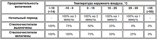
The heated windshield washer nozzles and outside rearview mirrors are always ready for operation when the ignition is on (position II.) The heaters are controlled using a PWM signal. (pulse width modulation), which is supplied at intervals of 30 seconds from the ATC module (automatic temperature control) to the coil of the relay for heating the windshield washer nozzles and outside mirrors, located in the distribution block of the BJB battery (.) When power is supplied to the relay, it closes the power supply circuit of the heaters. Power supply of the heaters ATC controller (automatic temperature control) regulates the duty cycle of PWM control signals (pulse width modulation) depending on the outside air temperature and the state of the windshield wipers. In the initial period after turning the ignition to position II, the ATC controller (automatic temperature control) sets the duty cycle of the PWM signal (pulse width modulation) equal to 100%. The duration of this period depends on the outside air temperature. After the initial period, the duty cycle is adjusted according to the condition of the windshield wipers.
Duty cycle of control signals for exterior mirror heaters
Adjustment
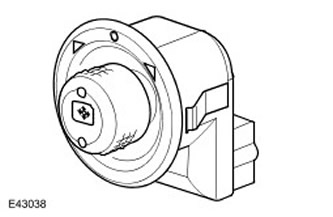
Each exterior mirror has two position adjustment motors. One motor is designed to adjust the position in the horizontal plane. (left-right), the second one is for adjustment in the vertical plane (up and down). The operation of the electric motors can be controlled using the outside mirror position controller located in the switch panel in the driver's door. Position adjustment is possible when the ignition switch is in position I or II.
The outside mirror position controller is a rotary switch with a joystick. The outside mirror for adjustment is selected by turning the switch to the left or right from the middle position. Tilting the switch results in power and ground being supplied to the corresponding motor and movement of the mirror in the corresponding direction. When the switch is tilted in the opposite direction, the polarity of the switch is reversed and the mirror moves in the opposite direction.
If the vehicle is equipped with a memory function, all connections from the outside mirror adjuster to the motors are routed through the memory controller. For more information, contact Seats (501-10 Seating)
External mirror position regulator
Recalling adjustments from memory
On vehicles equipped with the adjustment storage and recall system, each mirror drive motor is equipped with a feedback potentiometer that reports the current mirror position to the memory controller. The positions of the outside mirrors and the driver's seat are stored in memory in two ways:
- Manually, using the save and reset buttons.
- Automatically, when the easy-fit function is implemented and the ignition switch is turned from position II to position I.
The stored positions can be recalled from memory both while driving and when the vehicle is stationary. When the vehicle is stationary, briefly pressing the reset button brings the outside mirrors and the driver's seat to the position stored on the corresponding button, provided that the driver's door is open or the ignition switch is in position I or II. When the stored position is reached, a double gong signal sounds and the message appears on the information center display. (if configured). If you press the button while moving the mirror to the position recalled from memory (in any direction) adjusting the position, the mirror movement will stop immediately.
To prevent the position adjustment from being activated unintentionally while the vehicle is moving, the reset button must not only be pressed, but also held down.
If during movement to the recalled position the memory controller does not register a change in the signal from the feedback signal potentiometer for 100 ms or longer, the memory controller regards this as a jammed drive motor. If a jammed motor is detected, the use of this motor is stopped until the memory recall operation is completed. The motor can be activated again by pressing the switch in the desired direction.
Each time the ignition switch is turned from position II to position I, the memory controller automatically stores the position of the outside mirrors and the driver's seat along with the identification code of the ignition key. When the easy entry function is activated by unlocking the vehicle with the remote control, the memory controller compares the stored positions of the mirrors and the driver's seat with the current position for the key with this identification number. If there is a discrepancy, the memory controller moves the outside mirrors and the driver's seat to the position stored in the memory. If the lock button on the remote control is pressed during the easy entry operation, the movement of the mirrors and the seat will be stopped immediately.
The door lock command is transmitted to the memory controller from the CJB. (central switching unit) via the local LIN bus. The easy fit function can be enabled or disabled via the user settings menu. For more information, refer to the Information and Message Center (413-08)
Outside mirror
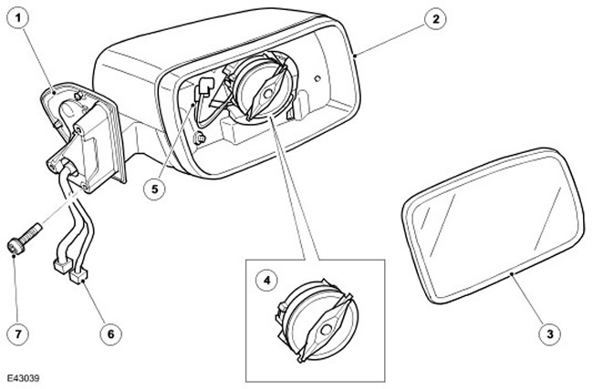
| Item name | Spare part catalog number | Description |
| 1 | - | Main frame |
| 2 | - | Mirror housing |
| 3 | - | Mirror glass |
| 4 | - | Motors for adjustment in vertical and horizontal planes |
| 5 | - | Lucar Heating Element Connectors |
| 6 | - | Electrical connectors C0319 and C1563 |
| 7 | - | Screw (x 3) |
Mirror tilt when reversing
On vehicles with the memory recall function, both outside mirrors automatically tilt downwards when reverse gear is engaged. (the ignition switch must be in position II).
When the selector is moved from the reverse position, the outside mirrors return to their original position. The tilt of the mirror when reversing is controlled by the memory controller.
The mirror tilt positions are programmed into the memory controller initially for each ignition key. If the position of the outside mirrors is changed with reverse gear engaged and the storage procedure is initiated, the previous positions will be replaced by the new ones. The next time reverse gear is engaged for this ignition key, the new mirror tilt position will be recalled. Storing the outside mirror positions with reverse gear engaged only affects the mirror tilt when reversing, the other settings stored in the memory remain unchanged.
On vehicles equipped with an automatic transmission, there is a half-second delay after the reverse gear is engaged and before the mirror begins to move. This delay prevents unnecessary movement of the mirrors when moving the selector from Park to Drive.
The mirror tilt function when reversing can be enabled or disabled via the user settings menu.
Folding mirrors
Mirrors with a folding function have an additional electric motor located in the hinge of the outside mirror. The operation of the folding motor is controlled by the position controller of the outside mirrors and the folding module.
The folding module is mounted directly outside the CJB unit. (central switching unit) and controls the power supply to the folding motors.
When the outside mirror position control is in the middle position (off), tilting the switch downward turns on the ground supply to the folding module. When the folding module receives the ground signal for the first time, the folding module supplies power and ground to the folding motor and the mirror folds. Pressing the switch again reverses the polarity of the power and ground supply and the motor unfolds the mirror. If the switch is pressed while the outside mirrors are moving, they stop and begin to move back to their original position. If one of the mirrors has been folded manually, the mirrors can be resynchronized by performing a folding and unfolding cycle.
To prevent the folding motor from overheating, the folding function is disabled for 3 minutes if this function is selected ten times within 60 seconds. If the tenth request occurs within 60 seconds, the mirrors will only open, the folding request will be ignored.
Connector C0907 folding module harness side
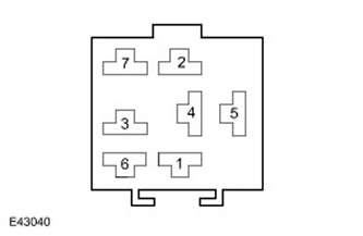
Contacts of connector C0907 of the folding module on the harness side
| Contact No. | Name | Input signal/output signal |
| 1 | "Positive" and "negative" contacts of the folding motor | Input signal/output signal |
| 2 | Folding signal from outside mirror position controller | Input |
| 3 | "Positive" and "negative" contacts of the folding motor | Input signal/output signal |
| 4 | Power supply from fuse 16 of the CJB unit (central switching unit) | Input signal |
| 5 | "Mass" of the system | Output signal |
| 6 and 7 | Not used | - |
Control system diagram (exterior mirrors without memory function)
NOTE: A = Normal Wiring; N = Medium Speed CAN Bus (local area network controller)
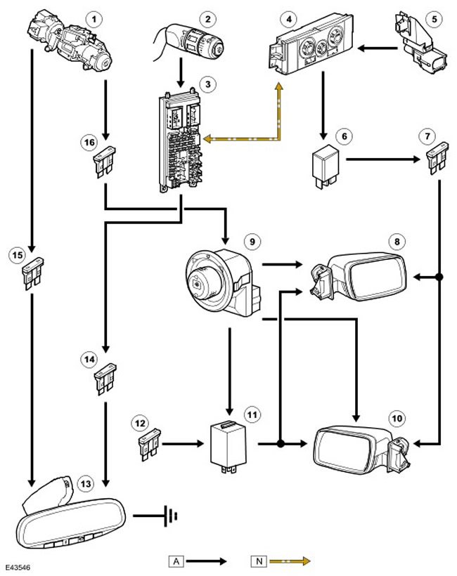
| Item name | Spare part catalog number | Description |
| 1 | - | Ignition switch |
| 2 | - | Windscreen wiper switch |
| 3 | - | CJB () |
| 4 | - | ATC module (automatic temperature control) |
| 5 | - | Outside air temperature sensor |
| 6 | - | Windscreen washer nozzle/external rear view mirror heater relay |
| 7 | - | Fuse 16E, BJB block (.) |
| 8 | - | Right outside mirror |
| 9 | - | External mirror position regulator |
| 10 | - | Left outside mirror |
| 11 | - | Folding module |
| 12 | - | Fuse 16P, CJB block (central switching unit) (battery powered) |
| 13 | - | Interior mirror |
| 14 | - | Fuse 5P, CJB block (central switching unit) (from the reverse signal relay) |
| 15 | - | Fuse 69P, CJB block (central switching unit) (ignition) |
| 16 | - | Fuse 33P, CJB block (central switching unit) (auxiliary nutrition) |
Control system diagram (exterior mirrors with memory function)
NOTE: A = Normal Wiring; N = Medium Speed CAN Bus (local area network controller); O = LIN bus
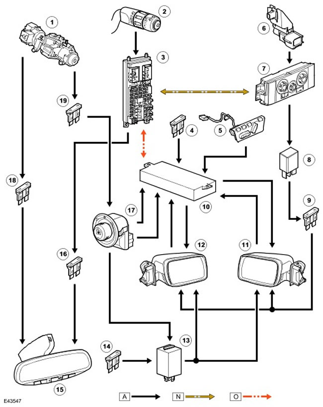
| Item name | Spare part catalog number | Description |
| 1 | - | Ignition switch |
| 2 | - | Windscreen wiper switch |
| 3 | - | CJB () |
| 4 | - | Fuse 46P, CJB block (central switching unit) (battery powered) |
| 5 | - | Seat adjustment and remote control with memory function |
| 6 | - | Outside air temperature sensor |
| 7 | - | ATC module (automatic temperature control) |
| 8 | - | Windscreen washer nozzle/external rear view mirror heater relay |
| 9 | - | Fuse 16E, BJB block (.) |
| 10 | - | Memory controller |
| 11 | - | Left outside mirror |
| 12 | - | Right outside mirror |
| 13 | - | Folding module |
| 14 | - | Fuse 16P, CJB block (central switching unit) (battery powered) |
| 15 | - | Interior mirror |
| 16 | - | Fuse 5P, CJB block (central switching unit) (from the reverse signal relay) |
| 17 | - | External mirror position regulator |
| 18 | - | Fuse 69P, CJB block (central switching unit) (ignition) |
| 19 | - | Fuse 33P, CJB block (central switching unit) (auxiliary nutrition) |
Comments on this article