Special tool
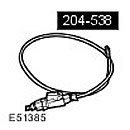 Pneumatic elastic element tester 204-538
 | 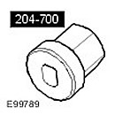 Front Air Strut Rod Nut Remover 204-700
 |
Removal
NOTE: This procedure should also be used when removing the front air spring.
1. Remove the front shock absorber assembly with the air spring. For more information, refer to
2.
NOTE: If no leak is found, inspect other areas of the air suspension for problems.
Check the tightness of the unit.
- Pressurise the module to 4 bar and use leak detection spray to check for pressure drop.
- If you suspect leaks, immerse the air spring and shock absorber assembly in a container of water to locate the air leak. Mark the leak location.
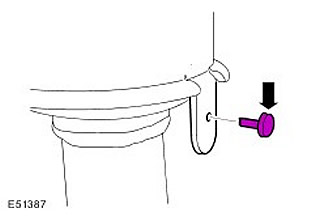
3. Remove the nylon retaining pin.
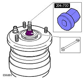
4. Using a special tool, unscrew the nut.
5. Remove the baffle plate.
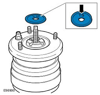
6.
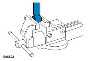
CAUTION: Install protective spacers on the vise jaws. Failure to follow this instruction may result in damage to the component.
CAUTION: Do not clamp the shock absorber tube. Failure to follow this instruction may result in damage to the component.
Clamp the front shock absorber assembly with the air spring in a vice.
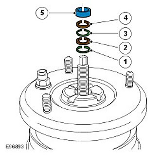
7. Remove and discard the three spacers and two sealing rings.
8. Remove the pneumatic spring. Using a soft-faced mallet, carefully tap the bushing support upward to remove it from the two sealing rings.
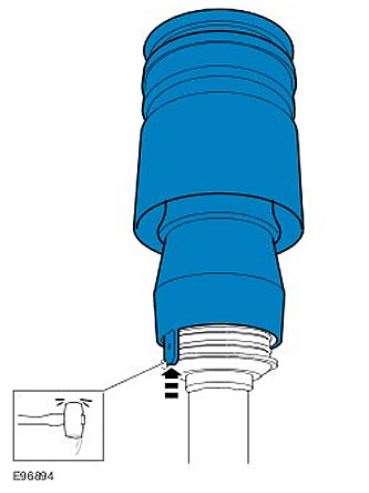
9.
NOTE: Mark the installation position.
Remove the shock plate and auxiliary spring.

10. Remove and discard the two large black O-rings from the lower seal housing.
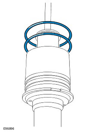
11. Remove the front shock absorber assembly with the air spring from the vice.
Installation
1.
CAUTION: Install protective spacers on the vise jaws. Failure to follow this instruction may result in damage to the component.
CAUTION: Do not clamp the shock absorber tube. Failure to follow this instruction may result in damage to the component.
Clamp the front shock absorber assembly with the air spring in a vice.
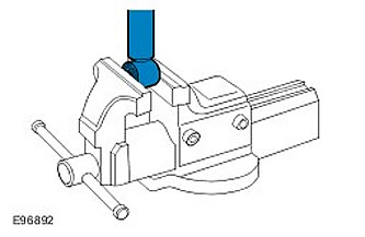
2.
CAUTION: Use compressed air and a lint-free cloth.
Clean the parts.
3. Lift the seal housing to open the O-ring kit. Make sure that the shock absorber body O-rings and spacer elements are fully seated on the spring plate.
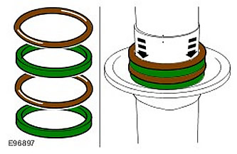
4.
CAUTION: Be careful not to damage the O-rings during installation.
Install new o-rings into seal housing. Apply loctite 8021 (silicone based oil) on the sealing rings.
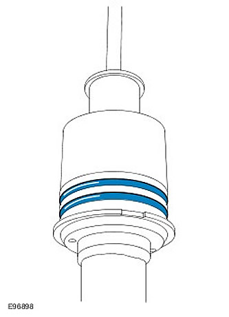
5.
NOTE: The elements must be installed in the original position marked during removal.
Install the bounce plate and auxiliary spring.
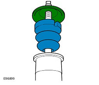
6. Install the air spring. Align the support sleeve with the first sealing ring, ensuring that the mounting lug fits correctly into the recess in the spring plate.
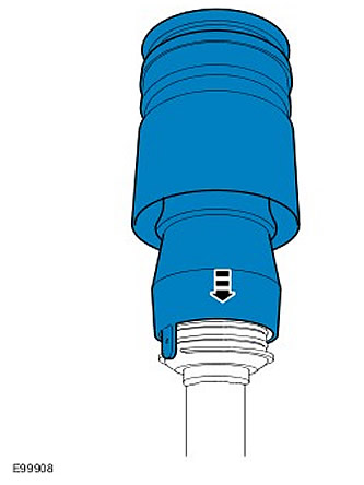
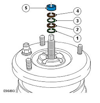
7.
CAUTION: Wrap the threads of the front air shock absorber with protective tape.
CAUTION: Be careful not to damage the O-rings during installation.
Install the elements in the following order:
- 1) Sealing ring
- 2) Remote element
- 3) Sealing ring
- 4) Remote element
- 5) Remote element
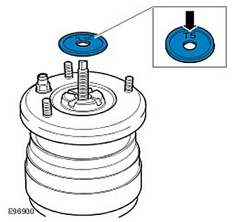
8.
NOTE: After assembly, the "T5" marking should be visible on the top surface of the baffle plate.
Install the baffle washer.
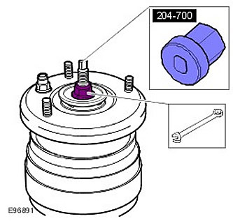
9. Using a special tool, screw on a new nut and tighten it to 98 Nm.
10.
CAUTION: The supplied air must not contain moisture.
CAUTION: If the air hose is turned during disassembly, it may not fill with air correctly. (only on one side)In this case, release the pressure and insert a suitable tool that will not damage the air hose or stem. (for example, a screwdriver handle), on the side opposite the bulge. Pump and release pressure until the air tube is filled with air correctly. (the air hose must be positioned symmetrically in the casing).
NOTE: To prevent damage when installing the support sleeve over the large black O-rings, use compressed air to inflate the air spring.
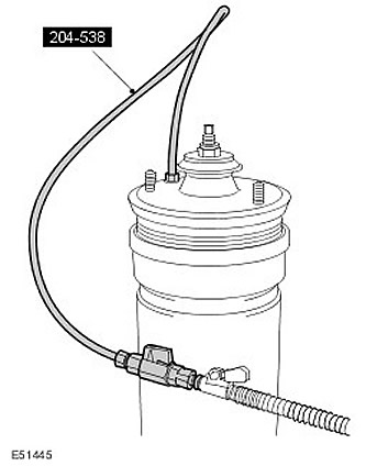
Using a special tool connected to a tire inflation compressor with a pressure gauge, apply a pressure of about 2 bar to the air spring so that the support sleeve is completely seated on the sealing rings.
11. Check the tightness of the unit.
- Pressurise the module to 4 bar and use leak detection spray to check for pressure drop.
- If you suspect leaks, immerse the air spring and shock absorber assembly in a container of water to locate the air leak.
12. Relieve the pressure and remove the special tool from the shock absorber/air spring assembly.
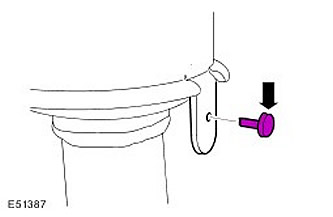
13. Install the nylon retaining pin.
14.
NOTE: Install a new air spring line fitting.
Install the front shock absorber assembly with the air spring.
Comments on this article