Dismantling
1. Disconnect "negative" battery terminal.
2. Remove the hood.
EXTERIOR PARTS, REPAIR WORKS, Bonnet.
3. Drain the engine coolant.
COOLING SYSTEM: MODIFICATION K, volume 1.8, ADJUSTMENTS, Coolant drain, system flushing and filling.
4. Drain the gearbox oil.
MANUAL TRANSMISSION - PG1, ADJUSTMENTS, Transmission oil change in the box.
5. Drain the oil from the transfer case.
TRANSFER BOX, ADJUSTMENTS, Changing the transmission oil in the transfer case: except for the North American market.
6. If necessary, drain the oil from the engine.
MAINTENANCE, MAINTENANCE, Engine oil and oil filter - K1.8.

7. Turn away 6 bolts of fastening of the right and left antisplash panels and remove panels.
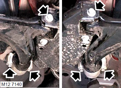
8. Loosen the nuts securing the rear of the lower suspension arm.
9. Turn away 2 bolts of fastening of a holder of plugs of the lower suspension arm.
10. Turn away bolts of plugs of an axis of the bottom lever.
11. Disconnect the lower arm from the beam.
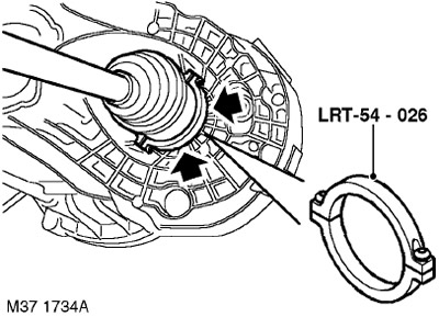
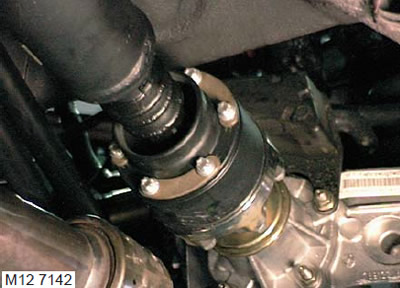
12. Install tool LRT-54-026 on the drive shaft inner joint. Using the lever, release the drive shafts from the transfer case and gearbox.
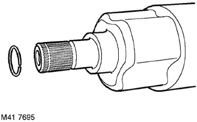
13. Remove and discard the driveshaft circlips.
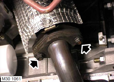
14. Turn away 2 nuts of fastening of a reception pipe to a final collector, take away a reception pipe and utilize a lining.
15. To facilitate subsequent reassembly, mark the position on the front propeller shaft.
16. Turn away 6 nuts and remove bolts of fastening of a cardan shaft to a leading flange of a distributing box.
17. Remove the propeller shaft from the transfer box drive flange and tie it aside.
CAUTION: Care must be taken when removing the three-roller joint from the transfer case. In order not to damage the cover, it must not be fully stretched, the hinge body must be protected from shock.
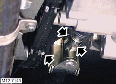
18. Remove shift rod pivot pin cover, remove and discard pin.
19. Disconnect the shift rod from the gear selector rod.
20. Turn away a bolt of fastening of a strut of a rod of a gear change to an arm of a distributing box, remove a strut from an arm.
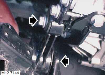
21. Turn away a bolt of fastening of the bottom crossbeam to an arm on the pallet.
22. Loosen the bolt securing the engine lower cross member to the rear beam, move the cross member away from the bracket on the pallet.
23. Disconnect the reversing light switch connector.
24. Disconnect the connector from the first gear engagement switch.
25. Disconnect the clamp securing the first gear contact sensor harness to the clutch slave cylinder bracket.
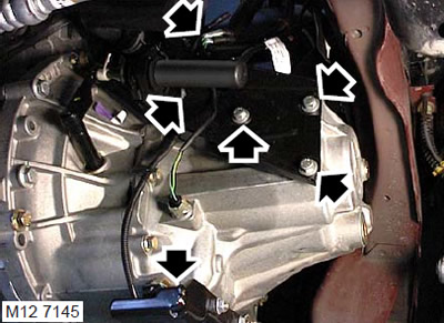
26. Turn away 3 bolts of fastening of an arm of the working cylinder to a transmission and fix an arm in the party.
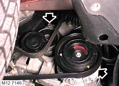
27. Models with air conditioning system: Using a 13 wrench, turn the accessory drive belt tensioner by the hexagon, fully clockwise to loosen the belt tension.
28. Models with A/C system: While holding the tensioner in this position, insert a pin, up to 3 mm in diameter, through the center of the hexagon into the back plate of the tensioner. Remove the belt from the compressor pulley.
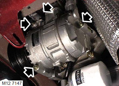
29. Models with air conditioning system: Disconnect the connector from the cooling compressor.
30. Models with air conditioning system: Remove the 3 bolts securing the air conditioning compressor to the common (with generator) bracket, remove the compressor from the bracket and secure it to the side.
31. Lower the car lift.
32. Remove the air cleaning filter.
FUEL SUPPLY OF PETROL ENGINE, REGULATIONS, Air filter, K1.8 engine.
33. Remove the battery pad.
SYSTEM OF STARTING THE ENGINE AND CHARGING THE BATTERY, REPAIR WORKS, Support tray - storage battery.
34. Remove the engine control unit (ECM).
ENGINE MANAGEMENT SYSTEM: MEMS, REPAIR WORK, Engine control unit (ECM): block for implementing ignition and fuel supply strategies.
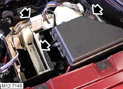
35. Disconnect the wire harness connector from the junction box.
36. Remove the air sleeve and rubber boot from the junction box for laying the harness.
37. Unfasten the 4 fastening latches of the platform in the mounting box, remove the platform and place it to the side.
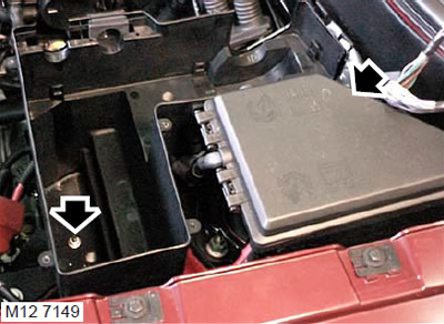
38. Turn away a nut, release a clamp and take out an installation box.
39. Remove the cover of the fuse box in the engine compartment.
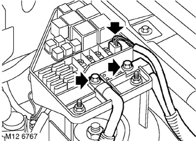
40. Turn away 2 bolts of fastening of tires of the storage battery and a starter to the block of safety locks.
41. Disconnect the connector from the fuse box.
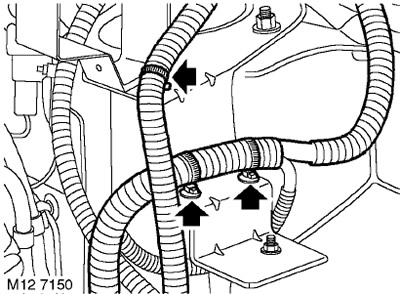
42. Disconnect the clamp that secures the battery bus bar to the junction box bracket.
43. Disconnect the 2 clamps securing the starter tire to the junction box bracket.
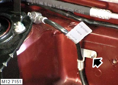
44. Loosen the tire mounting nut "masses" to the body and remove the tire from the stud.
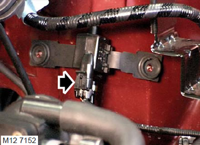
45. Disconnect the connector from the canister purge solenoid valve.
46. Lay a rag near the fuel supply hose so that spilled fuel does not spread.
CAUTION: Fuel leakage is inevitable during this operation. Take safety precautions to prevent fire or explosion.
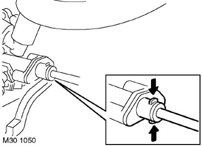
47. Disconnect the fuel supply hose from the fuel rail.
CAUTION: Always plug fittings and openings to keep dirt out of the system.
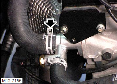
48. Loosen the clamp and disconnect the purge hose from the intake manifold.
49. Remove the throttle cable adjusting nut from the bracket.
50. Remove the cable from the damper control sector.
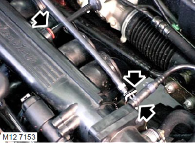
51. Press on the plastic shoulders of the connector and disconnect the vacuum brake booster hose from the intake manifold.
52. Loosen the clamps and remove the heater inlet and outlet hoses.
53. Turn away a collar and disconnect the top hose from an elbow branch pipe of system of cooling.
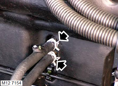
54. Loosen the clamp and disconnect the expansion tank hose from the intake manifold.
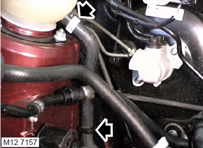
55. Loosen the clamp and disconnect the hose from the bottom of the expansion tank.
56. Disconnect the expansion tank from the mount on the body.

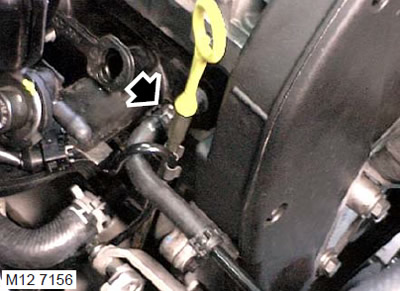
57. Turn away 2 bolts of fastening of an epiploon cover to a head of cylinders and remove a cover.
58. Install the lifting eye LRT-12-135/1 in place of the camshaft oil seal cover, screw in and tighten the bolts.
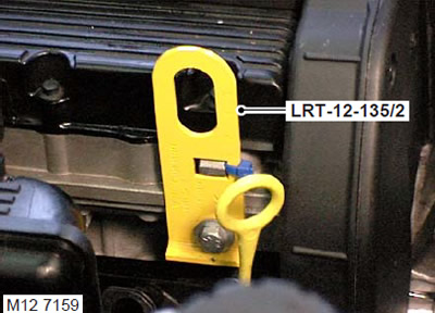
59. Install lifting eye LRT-12-135/2 on the front part of the cylinder head and fasten it with bolts.
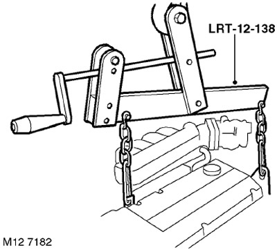
60. Attach the LRT-12-138 adjustable yoke hoist to the engine.
61. Turn away a bolt of fastening of a crossbeam to the left support of the engine.
62. Turn out a through bolt of fastening of the left support of the engine to an arm.
63. Turn away four bolts of fastening of the left arm of a support to a body.
64. Turn away a through bolt of fastening of the left support of the engine to an arm and remove an arm.
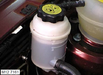
65. Remove the power steering reservoir from the bracket and secure it to the side.
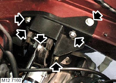
66. Turn out a bolt of fastening of the top right cross-beam of the engine to the top bracket on the engine.
67. Loosen the bolt securing the upper right engine cross member to the body and move the cross member away from the upper bracket.
68. Unscrew the nut securing the top bracket to the right hydraulic support, unscrew the two bolts securing the top bracket to the engine and remove the top bracket.
69. Raise the engine with the gearbox just enough to provide access to the power steering pump.
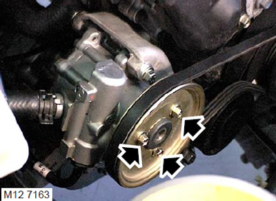
70. Loosen the three bolts securing the power steering pump pulley.
71. Using a 13 mm wrench, turn the power steering pump belt tensioner and insert a 4 mm pin through the center of the hexagon into the back plate of the tensioner. Remove the power steering pump belt.
72. Turn away 3 bolts of fastening of a pulley of the pump of the hydraulic booster and remove a pulley.
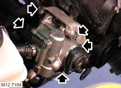
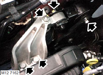
73. Turn away 5 bolts of fastening of the pump of the hydraulic booster of a steering, take away the pump and fix it.
74. With the help of a partner, avoiding obstacles, lift the engine with the gearbox out of the engine compartment.
Installation
1. Attach the LRT-12-138 adjustable head hoist to the motor.
2. With the help of a partner, lower the engine with the gearbox into the engine compartment until the power steering pump can be installed.
3. Install the power steering pump on the bracket, screw in the bolts and tighten them to a torque of 25 Nm.
4. Install the pulley on the power steering pump, screw in the bolts and tighten them to a torque of 10 Nm.
5. Put the belt on the power steering pulley, remove the tensioner, remove the pin and release the tensioner.
6. Lower the engine with gearbox to the attachment points.
7. Install the bracket on the left engine mount, insert the through bolt but do not tighten at this stage.
8. Install the left engine bracket on the body, screw in the bolts and tighten them to a torque of 45 Nm.
9. Tighten the through bolt of the left engine mount to 80 Nm.
10. Adjust the position of the motor to fit the top bracket.
11. Install the upper bracket on the right hydraulic support and on the engine, screw in the bolts and tighten them to a torque of 170 Nm, fit the nuts and tighten them to a torque of 85 Nm.
12. Lower the chains, unhook and remove the LRT-12-138 yoke.
13. Install the upper right cross member on the upper bracket, screw in the bolt and tighten it to 80 Nm.
14. Tighten the bolt securing the upper cross member to the body to 80 Nm.
15. Attach the hydraulic booster reservoir to the bracket.
16. Turn away a bolt of fastening of a lifting eye LRT-12-135/2 to a forward part of a head of cylinders and remove an eye.
17. Turn away 2 bolts of fastening of a lifting eye LRT-12-135/2 to a back part of a head of cylinders and remove an eye.
18. Wipe the camshaft oil seal cover and mating surface.
19. Install the stuffing box cover, screw in the bolts and tighten them to a torque of 25 Nm.
20. Attach a hose to the bottom of a broad tank and fix it with a collar. Attach the hose to the clamp on the body.
21. Attach a hose of a broad tank to an inlet collector and fix it with a collar.
22. Connect the top hose to the elbow and secure with a clamp.
23. Connect the heater inlet and outlet hoses and secure them with a clamp.
24. Attach a hose of the vacuum amplifier of a brake system to an inlet collector.
25. Fasten the throttle control cable to the gas sector and the cable sheath to the bracket.
26. Attach the fuel supply hose to the fuel rail.
27. Connect the connector to the canister purge solenoid valve.
28. Put the ground wire on the stud, screw on the nut and tighten it. Tightening torque 9 Nm.
29. Lay the battery bus bar on the junction box bracket and secure the bus bar with a clamp.
30. Connect the battery and starter tires to the fuse box in the engine compartment, screw in the bolts and tighten them to 8 Nm.
31. Attach 2 starter bar clamps to the junction box bracket.
32. Connect the connector to the fuse box.
33. Replace the fuse box cover in the engine compartment.
34. Install the junction box, secure it with a latch, screw on the nut and tighten it with a torque of 9 Nm.
35. Place the platform into the junction box and secure it with the fasteners.
36. Attach the air sleeve and rubber boot for laying the harness to the mounting box and secure them.
37. Attach the wire harness to the junction box.
38. Install the engine control unit (ECM).
ENGINE MANAGEMENT SYSTEM: MEMS, REPAIR WORK, Engine control unit (ECM): block for implementing ignition and fuel supply strategies.
39. Raise the car on a lift.
40. Models with air conditioning system: Install the air conditioning compressor on the bracket, screw in the bolts and tighten them to a torque of 25 Nm.
41. Models with air conditioning system: Connect the electrical connector to the air conditioning compressor.
42. Models with A/C system: Pull out the belt tensioner, remove the pin, slide the belt over the compressor pulley and release the belt tensioner.
43. Establish an arm of fastening of the working cylinder of coupling on a transmission, screw in bolts and tighten them the moment of 25 Nanometers.
44. Attach the connector to the first gear contact switch and secure the harness with a clamp on the slave cylinder bracket.
45. Connect the reversing light switch connector.
46. Install the lower cross member on the pallet bracket, screw in the bolts and tighten them to a torque of 80 Nm.
47. Tighten the bolt securing the lower cross member to the rear beam to 80 Nm.
48. Install the shift rod spacer, screw in the bolt and tighten it to 25 Nm.
49. Install the shift shaft onto the select shaft, install a NEW pivot pin and replace the cap.
50. Install the propeller shaft on the transfer case drive flange so that the previously made marks line up. Tighten nuts and bolts to 42 Nm.
51. Put a new gasket on the exhaust manifold flange, install the exhaust pipe and tighten the nuts to 75 Nm.
52. Wipe the spline of the drive shaft and mating splines in the gearbox.
53. Insert the drive shafts into the transfer case and into the gearbox, making sure that the retaining rings of each shaft fit into their sockets.
54. Insert the bushings of the lower arm, screw in but do not tighten the bolts.
CAUTION: Nuts and bolts must be tightened when the weight of the vehicle is supported by the suspension.
55. Clean out the rubber bushing in the subframe and the mating surfaces.
56. Align the bushing sockets so that the barrel pin is correctly positioned. Screw in the bolts and tighten them to a torque of 105 Nm.
57. Install the left and right mudguards, screw in and tighten the mounting bolts.
58. Lower the car.
59. Tighten the lower arm front bushing bolts. Tightening torque 175 Nm.
60. Tighten the lower arm rear bushing bolts. Tightening torque 140 Nm.
61. Replace the battery tray.
SYSTEM OF STARTING THE ENGINE AND CHARGING THE BATTERY, REPAIR WORKS, Support tray - storage battery.
62. Adjust the throttle cable.
FUEL SUPPLY OF PETROL ENGINE, ADJUSTMENTS, Throttle control cable - check and adjustment: K1.8 engine.
63. Install the air cleaner.
FUEL SUPPLY OF PETROL ENGINE, REGULATIONS, Air filter, K1.8 engine.
64. If necessary, add oil to the engine.
MAINTENANCE, MAINTENANCE, Engine oil and oil filter - K1.8.
65. Fill oil into the transfer case housing to the required level.
TRANSFER BOX, ADJUSTMENTS, Changing the transmission oil in the transfer case: except for the North American market.
66. Fill the gearbox with oil.
MANUAL TRANSMISSION - PG1, ADJUSTMENTS, Transmission oil change in the box.
67. Add coolant to the cooling system.
COOLING SYSTEM: MODIFICATION K, volume 1.8, ADJUSTMENTS, Coolant drain, system flushing and filling.
68. Attach "negative" battery terminal.
69. Install the hood.
EXTERIOR PARTS, REPAIR WORKS, Bonnet.
Comments on this article