Contents: Yield strength ⇩ Tensile strength ⇩ Welding ultra-strong steel ⇩ Brazing in an inert gas environment ⇩
Most modern cars are built using different grades of steel, which allows for the optimization of the body structure (collision, safety, rigidity, reduced fuel consumption, etc.).
Steels are divided into several groups according to their tensile strength and yield strength (the force required for plastic deformation of the material).
Yield strength
The yield strength determines the force at which the metal loses elasticity and begins to plastically deform without subsequent restoration of shape.
Tensile strength
The tensile strength defines the force at which a stretched specimen breaks.
Dual phase (DP) steel can meet either VHSS or EHSS classifications, depending on the grade.
| Steel grade | Yield strength |
| Mild low carbon steel (MS) | Yield strength up to 180 MPa |
| High Strength Steel (HSS) | Steel with yield strength up to 280 MPa |
| Very High Strength Steel (VHSS) | Steel with yield strength up to 380 MPa |
| Extra High Strength Steel (EHSS) | Steel with yield strength up to 800 MPa |
| Ultra High Strength Steel (UHSS) | Steel with a yield strength of over 800 MPa |
Welding ultra-strong steel
Welding ultra-high strength steel requires the use of welding equipment that allows the following welding parameters.
Brazing in an inert gas environment
When performing MIG brazing, use a welding machine of the following type that meets the specified specification: Fronius Trans Plus Synergic 2700 4 R/Z/AL MIG welding machine, with CuSi3 wire (DIN 1733) diameter of 1.0 mm and using stage 4, which corresponds to a current of 92 A and a feed speed of 4.6 m/min. Shielding gas L1 = pure argon (DIN 439).
Steels used in the body structure:
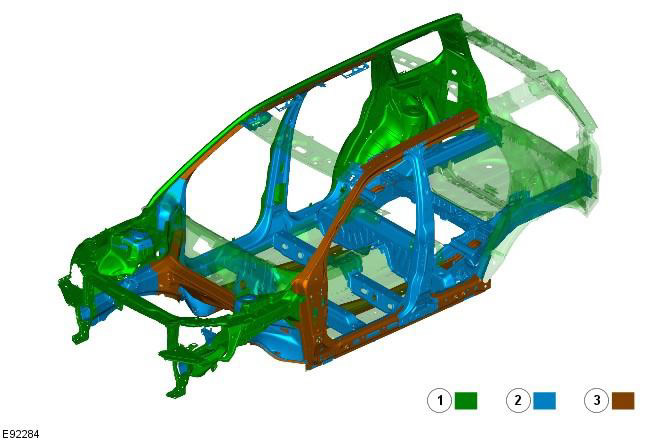
| Element | Steel grade |
| 1 | Mild (low carbon) steel (SS) |
| 2 | High Strength Steel (HSS) |
| 3 | Extra High Strength Steel (EHSS) |
[The article was copied from this resource: www.LRman.ru]
NOTE: The additional use of DP600 (EHSS) steel in the "ring frame" of the side panel reinforcements and in the rear and front side members provides greater strength in a frontal or side impact.
NOTE: When installing the outer side panels, A-pillar, B-pillar, sill panel and rear side panel, it is necessary to hard solder the grooves where these elements adjoin their inner reinforcement panels.
NOTE: The groove size is 20mm x 8mm, with a distance between grooves of 30mm. The grooves should be made in accordance with this interval. Where this is not possible due to dents in the panel, the groove should be made at the location of the original spot weld.
Sidebar
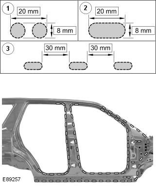
| Element | Name |
| 1 | To make a base for the groove, drill 2 holes 8mm. |
| 2 | Rout a groove measuring 20mm x 8mm |
| 3 | The distance between the grooves should be 30mm |
NOTE: Brazing in a protective atmosphere is carried out at a temperature of 650°C - 950°C. To ensure that the ultra-high-strength steel does not lose its properties, the temperature should not exceed 950°C.
Perform hard soldering of the grooves using the Fronius Trans Plus Synergic 2700 4 R/Z/AL MIG welding machine, with CuSi3 wire (DIN 1733) diameter of 1.0 mm and using stage 4, which corresponds to a current of 92 A and a feed speed of 4.6 m/min. Shielding gas L1 = pure argon (DIN 439).
Clean the weld in the groove with a belt sander using a 60/80 grit belt.
Comments on this article