Contents: Navigation system computer ⇩ Touch screen display ⇩ Global Positioning System (GPS)…⇩ VICS Beacon Antenna - Japan Only ⇩ Control panel and control module of…⇩ On-board audio module ⇩
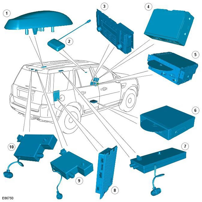
| Pos. | Spare part number | Name |
| 1 | - | Global Positioning System (GPS) Antenna |
| 2 | - | Roadside Infrared and Radio Message Receiving System (VICS) Beacon Antenna - Japan Only |
| 3 | - | Control panel and control module of the infotainment system |
| 4 | - | Touch screen display |
| 5 | - | On-board audio module |
| 6 | - | Navigation system computer |
| 7 | - | AM (Amplitude Modulation) / FM (Frequency Modulation) Antenna Booster - Non-Diversity Reception System, or AM/FM Diversity Reception System Antenna Booster |
| 8 | - | Sound amplifier |
| 9 | - | VICS/TMC Antenna Booster |
| 10 | - | FM Dual Antenna Amplifier for Diversity Reception Setup |
The navigation system provides audio and visual route instructions to help the driver reach his destination. The system allows the driver to select the desired route, giving preference to major or minor roads, or motorways with the option of choosing one of three routes. In addition, the system contains information on hospitals, museums, monuments and hotels. Geographical maps and related information are recorded on a DVD, and the driver is offered the best route with a detailed description of the direction of travel, intersections and detours.
The driver controls the navigation system using a touchscreen. Control signals from the touchscreen are transmitted via the MOST bus (Media Orientated System Transport) to the infotainment control module and from there via the MOST bus to the navigation computer. Navigation computer via a dedicated GVIF interface (Gigabit Video Interface) transmits a video signal to the touch screen.
Cars equipped with navigation systems are also equipped with additional systems for receiving road information. The system model depends on the market:
- Europe - Road Message Channel (TMC).
- Japan - Roadside Infrared and Radio Message System (VICS).
- North America - no additional system installed.
Navigation system computer
[The article was copied from a resource lrman.ru]
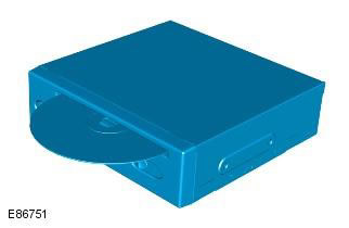
The navigation system computer, located under the right front seat, has a DVD drive for reading maps from DVD discs (disc version varies by region). The DVD loading slot is accessible from the rear of the seat.
The button located next to the DVD slot is used to eject the DVD from the unit. Before ejecting the disc, you must slide the slot cover to the side. If the ignition is on or the infotainment system is in the one-hour mode, the DVD is ejected by pressing the button once.
The navigation computer, connected to the MOST bus, generates its own graphic images and transmits them to the touch screen via a dedicated GVIF bus (Gigabyte Video Interface).
The navigation computer also includes:
- GPS receiver
- VICS Receiver (Japan only)
- Traffic Management Channel (TMC) Receiver
The GPS receiver receives information from one to eight satellites at a given time. This information is received by the GPS antenna. The built-in GPS receiver is used to calculate position (i.e. latitude, longitude and altitude), direction and speed.
The navigation computer has a semiconductor piezoelectric gyro sensor that measures the vehicle's movement along the vertical axis. The gyro sensor operates on the principle of the Coriolis force. The Coriolis force is the force that occurs to accelerate bodies moving from the axis of rotation in the direction of the axis's rotation.
To calculate the current position of the car, its direction and speed of movement, the computer uses:
- speed signals transmitted via the high-speed CAN bus from the ABS module to the MOST bus
- signals transmitted from the GPS receiver and gyro sensor
For the Japanese market, the navigation computer is equipped with a VICS receiver. The VICS receiver receives information from the VICS beacon antenna located in the center of the instrument panel and from the electric FM antenna. With this data, the VICS system monitors traffic information from roadside transmitters and adjusts the route if necessary to avoid traffic jams.
For some European countries, the navigation computer is equipped with a Traffic Message Channel (TMC) receiver. The TMC receiver decodes the TMC data. The navigation computer then displays this information on the touch screen and changes the navigation system input to avoid traffic jams. The TMC data is sent to an electric FM antenna.
To save the settings and configuration data when the system is turned off, the navigation computer uses a non-volatile memory device. Memorization is performed immediately before turning off.
Touch screen display
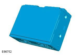
The touch screen is located in the center of the instrument panel and is a dedicated interface for the navigation system. The touch screen is not designed to work with any other systems in the car. The screen is a liquid crystal display (LCD) with a diagonal of 7 inches; its resolution is 800 x 480 pixels, format 15:9. The touch screen is connected to the infotainment system via the MOST bus. MOST is a fiber-optic bus designed for high-speed transmission of commands and sound in the multimedia system.
The touch screen handles its own video processing, but all graphical navigation information comes from the navigation computer via a dedicated GVIF serial bus (Gigabit Video Interface).
The navigation system control signals from the touch screen are transmitted via the MOST bus to the navigation computer.
Global Positioning System (GPS) Antenna

The Global Positioning System (GPS) antenna is located at the rear of the vehicle's roof. The GPS antenna is connected to the navigation computer via a single coaxial cable, receives signals from the GPS satellites, and transmits them to the receiver built into the navigation computer for processing.
The GPS antenna may lose signal from GPS satellites:
- In a hilly area and on an avenue with tall trees
- In the area of high-rise buildings
- In multi-storey car parks
- In the garages
- In the tunnels
- On the bridges
- During a downpour or thunderstorm
In this case, the navigation system continues to operate until the connection is restored, based only on the information recorded on the DVD disc.
For more information, please refer to the chapter: Antenna (415-02, Description and Operating Principle).
VICS Beacon Antenna - Japan Only
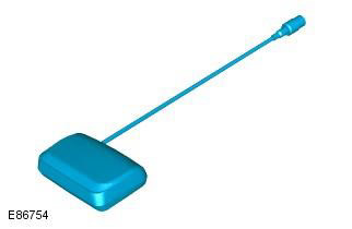
The VICS infrared antenna is mounted on the top of the instrument panel. The antenna receives infrared and radio frequency signals from transmitters installed along the road. The antenna is connected to the navigation computer with a built-in VICS receiver.
For more information, please refer to the chapter: Antenna (415-02, Description and Operating Principle).
Control panel and control module of the infotainment system
The control panel contains the audio system switches and the telephone control unit. The navigation system is controlled via the touch screen using signals transmitted via the MOST bus. When the hardware buttons on the control panel are pressed, the CAN signals are transmitted to the infotainment control module, which transmits the signals to the corresponding MOST bus module.
The infotainment control module is a gateway between the medium speed CAN bus and the infotainment MOST bus.
For more information, please refer to the chapter: Audio System (415-01, Description and Function).
On-board audio module
Audio signals are sent along the MOST ring circuit from the on-board audio module to the amplifier.
For more information, please refer to the chapter: Audio System (415-01, Description and Function).
Comments on this article