car logo Ford
car logo Volkswagen
car logo BMW
car logo Opel
car logo Audi
car logo Toyota
car logo Peugeot
English Русский
Български
Беларускі
Український
Српски
Hrvatski
Română
Polski
Slovenský
Magyar


Main
Freelander
Discovery
Range Rover
Defender
Contacts
Articles

Disassembling the gearbox (Discovery 1)

 
  • Main
  • Discovery
  • Discovery 1
  • Transmission
  • Manual gearbox LT 77
  • Disassembling the gearbox
 
        0  
Contents: Shift mechanism housing ⇩ Fifth gear housing ⇩ Fifth gear gears of the secondary…⇩ Main body of the checkpoint ⇩ Primary, secondary and reverse gear…⇩ Disassembling the secondary shaft ⇩ Front gearbox cover ⇩ Gearbox spacer ⇩ Fifth gear housing ⇩ Shift mechanism housing ⇩

Shift mechanism housing


1. Disconnect the gearbox from the transfer case.

2. Unscrew the screws and remove the top cover of the mechanism.
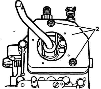
2. Unscrew the screws and remove the top cover of the mechanism.


3. Remove the transfer case shift mechanism housing.

4. Remove the gearbox shift housing.
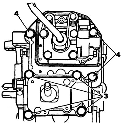
4. Remove the gearbox shift housing.


Fifth gear housing


1. Remove the oil seal cover retaining ring.
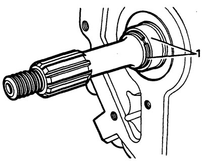
1. Remove the oil seal cover retaining ring.


2. Using a special tool, remove the cover.
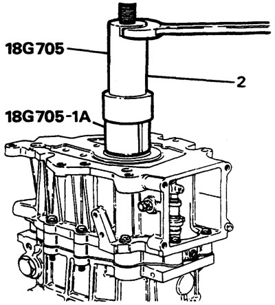


2. Using a special tool, remove the cover.


3. Unscrew the bolts and remove the housing.

4. Secure the center spacer with two 8x35mm bolts.

5. Remove the rod leash from the rod.
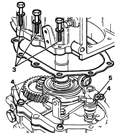
5. Remove the rod leash from the rod.


Fifth gear gears of the secondary and intermediate shafts


1. Remove the secondary shaft seal ring.

2. Remove the oil pump drive shaft.

3. Disconnect the mounting clips from the fork.

4. Remove the fifth gear sleeve.

5. Remove the fork bracket.
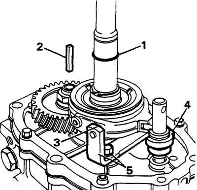
5. Remove the fork bracket.


6. Install the holder.


7. Install the fixture for fixing the intermediate shaft fifth gear.

8. Unscrew the lock nut.
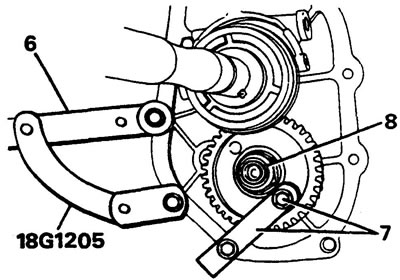
8. Unscrew the lock nut.


9. Remove the fifth gear synchronizer retaining ring.

10. Install the puller and adapter as shown.
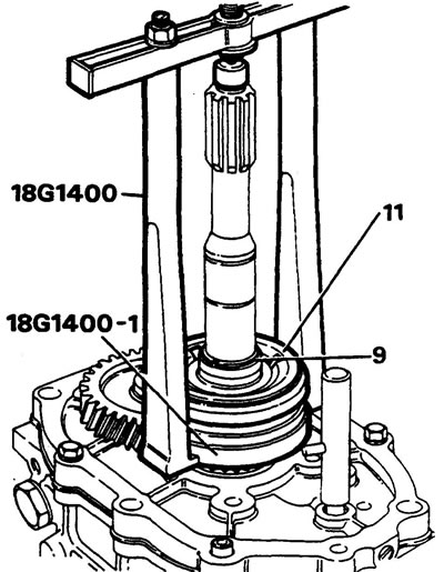
10. Install the puller and adapter as shown.


Caution: Make sure the adapter and puller are installed correctly.


11. Remove the fifth gear synchronizer assembly.
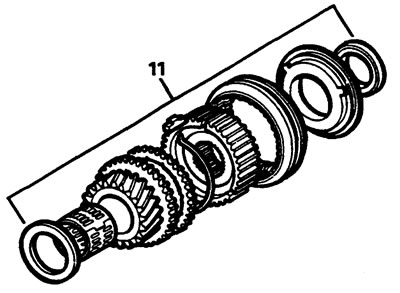
11. Remove the fifth gear synchronizer assembly.


12. Remove the intermediate shaft using special tools.
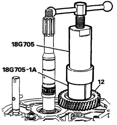


12. Remove the intermediate shaft using special tools.


Main body of the checkpoint


1. Install the reverse gear shaft lock "A" onto the gearbox spacer.
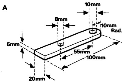
1. Install the reverse gear shaft lock «A» onto the gearbox spacer.


2. Screw the threaded pins "B" into the housing.
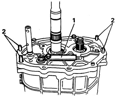
2. Screw the threaded pins «B» into the housing.


3. Turn the body over and place it on stand "E", aligning the recesses in the stand with the pins.

4. Disconnect the shift fork shaft bushing lock.
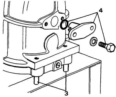
4. Disconnect the shift fork shaft bushing lock.


5. Unscrew the bolts and remove the front cover and gasket.
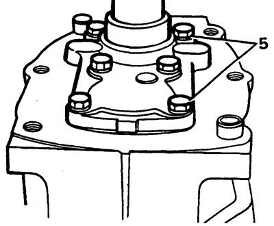


5. Unscrew the bolts and remove the front cover and gasket.


6. Remove the adjusting washers.

7. Unscrew the bolts and separate the housing.

8. Secure the spacer to the stand with a bolt and nut.
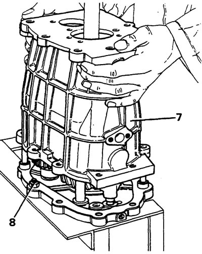
8. Secure the spacer to the stand with a bolt and nut.


Primary, secondary and reverse gear shafts


1. Remove the retainer and reverse gear shaft.
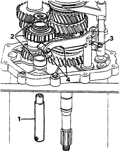
1. Remove the retainer and reverse gear shaft.


2. Remove the thrust washer, reverse gear and bushing.

3. Remove the reverse gear lever locking pin.


4. Remove the lever and shoe.

5. Remove the input shaft and the fourth gear synchronizer ring.

6. Remove the intermediate shaft as shown in the figure
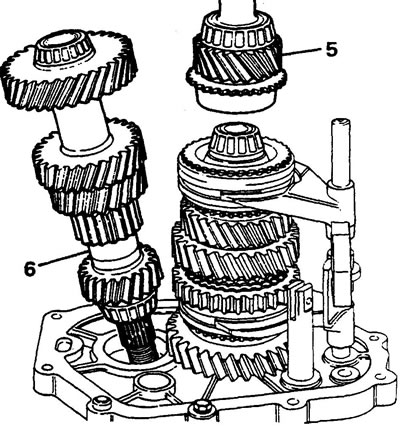
6. Remove the intermediate shaft as shown in the figure


7. Unscrew the plug and remove the outer spring and ball.
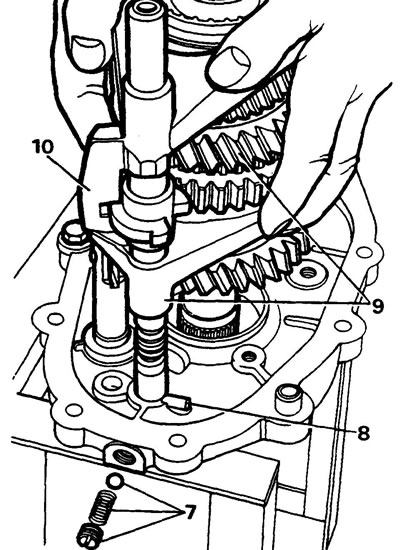
7. Unscrew the plug and remove the outer spring and ball.


8. Align the fifth gear shaft pin with the groove in the spacer.

9. Remove the secondary shaft, pinion gears and forks as shown.

10. Remove the gear fork.

11. Remove the inner ball and spring from the hole in the spacer.
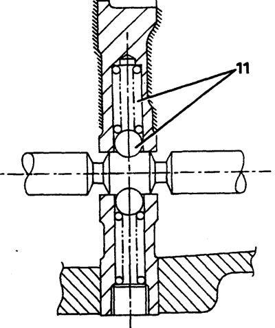
11. Remove the inner ball and spring from the hole in the spacer.


12. Using special tools, remove the intermediate shaft bearings.
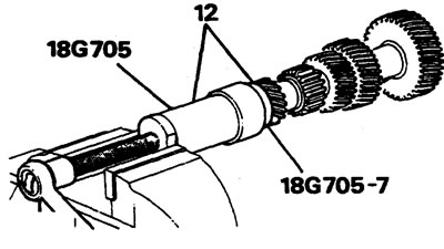


12. Using special tools, remove the intermediate shaft bearings.


Disassembling the secondary shaft


1. Remove the first gear retaining ring.
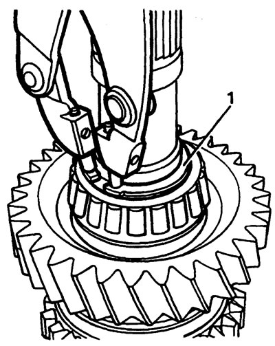
1. Remove the first gear retaining ring.


2. Remove the roller bearing, washer, needle bearing, first gear sleeve, cone ring and synchronizer rings.

3. Remove the retaining ring to remove the first and second gear synchronizer.
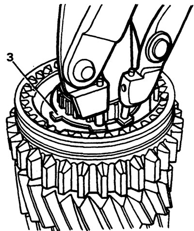
3. Remove the retaining ring to remove the first and second gear synchronizer.


4. Use a puller to remove the first gear from the shaft.
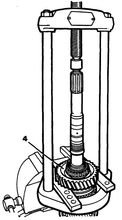


4. Use a puller to remove the first gear from the shaft.


5. Remove the synchronizer rings.

6. Using a puller, lift the bearing, 3/4 gear synchronizer, 2nd and 3rd gear gears.
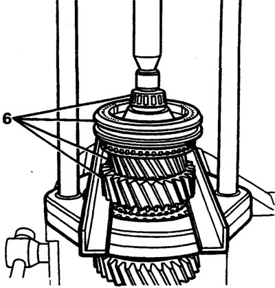
6. Using a puller, lift the bearing, 3/4 gear synchronizer, 2nd and 3rd gear gears.


7. Remove the washer, 3/4 gear synchronizer, 3rd gear locking ring, needle bearings, bushing and 2nd gear.

8. Remove the retaining rings, the second gear cone ring bushing.
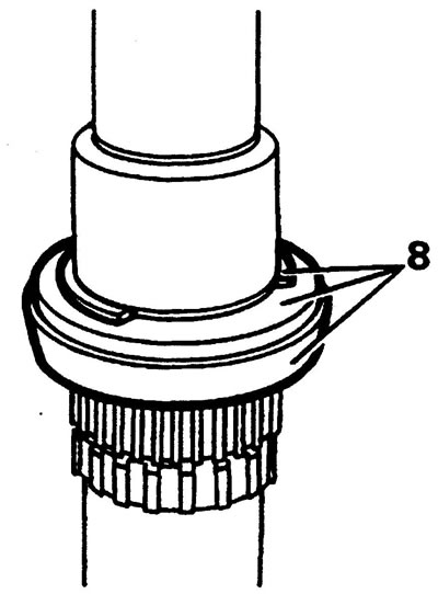
8. Remove the retaining rings, the second gear cone ring bushing.


Front gearbox cover


1. Remove the oil seal from the cover; do not install the new oil seal yet.
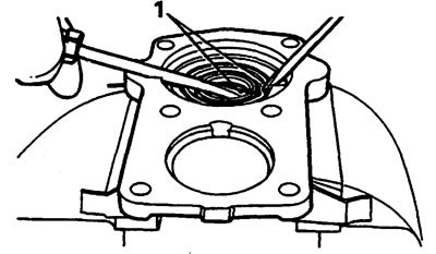
1. Remove the oil seal from the cover; do not install the new oil seal yet.


Gearbox spacer


1. Remove the bearing races.

2. Check components for damage and wear.

3. Carefully install the reverse gear shaft and check the gap between the lever and the shoe, which should not be more than 0.2 mm.
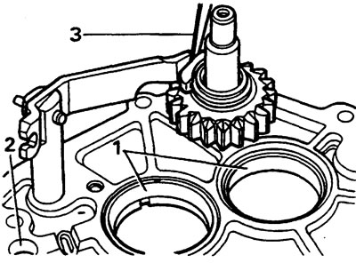
3. Carefully install the reverse gear shaft and check the gap between the lever and the shoe, which…


Fifth gear housing


1. Check components for damage and wear.

2. Unscrew the pump cover, check, replace components if necessary.
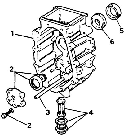
2. Unscrew the pump cover, check, replace components if necessary.


3. Check the feed tube but do not remove it.

4. Remove the drain pipe, clean the filter, change it if necessary.

5. Replace the oil seal.

6. Replace the ferroasbestos bushing.

Caution: The bushing contains asbestos, do not attempt to clean it.


7. Install the new bushing with the holes facing inwards/away from the oil seal.

Caution: If the bushing is installed incorrectly, oil may leak through the seal.
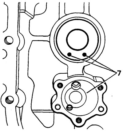

Caution: If the bushing is installed incorrectly, oil may leak through the seal.


8. If the housing is changed, replace the Allen screws and install them with Loctite.
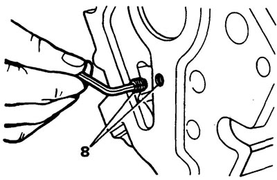
8. If the housing is changed, replace the Allen screws and install them with Loctite.


9. Install the new oil seal, lips inward, using a drift.
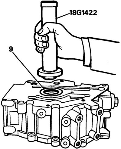
9. Install the new oil seal, lips inward, using a drift.


10. Assemble the pump gears and install the cover.
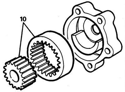
10. Assemble the pump gears and install the cover.


11. Check the guide, replace if necessary.
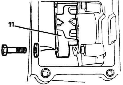
11. Check the guide, replace if necessary.


Shift mechanism housing


1. Remove the return plunger and washers.

2. Unscrew the spring fixing bolts.
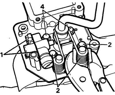
2. Unscrew the spring fixing bolts.


Caution: Be careful to avoid injury.


3. Remove the two springs.

4. Unscrew the mounting bolts to access the bottom of the lever.

5. Check the guide pins and grooves for damage.
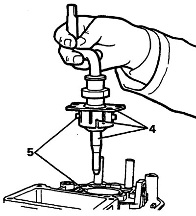
5. Check the guide pins and grooves for damage.


6. Turn the case over and check the lock mounting bolts.

7. Remove the oil seal and replace it with a new one, with the lips facing inward.
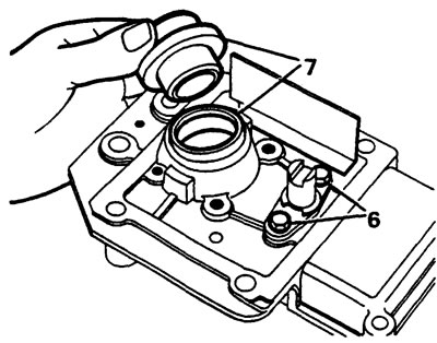
7. Remove the oil seal and replace it with a new one, with the lips facing inward.


8. Check the springs and replace if necessary.

9. Lubricate the lever ball with lithium-based grease, replace the plastic bushing.

10. Install the lever.

11. Install the limit plate

Note: Apply Loctite to the threads of the two short bolts and install them into the front pair of holes. Tighten the bolts to prevent the plate from shifting while installing the springs.


12. Place the springs with their long ends over the lever.

13. Check the operation of the return plunger.

Note: Apply a load of 45-55 kg to the plunger, it should work without jamming, the plunger is non-separable and can be replaced as an assembly.


14. Check the operation of the reverse light switch.
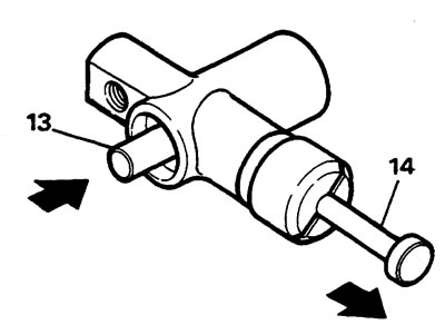
14. Check the operation of the reverse light switch.


This article is available at russian, bulgarian, belarusian, ukrainian, serbian, croatian, romanian, polish, slovak, hungarian
Article review: Konstantin Nazarov


Previous articles
LT 77 Manual Transmission — Description
Signs of gearbox malfunctions and possible ways to fix them
Removal and installation the gearbox

Current article
Disassembling the gearbox

Next article
Gearbox assembly


Similar articles from Land Rover repair manuals:
• Gearbox serial number Freelander 2 (2006-2014)
• Engine and gearbox Freelander 1 (1997-2006)
• Rear gearbox seal Range Rover 3 (2001-2012)
• Disassembling a manual gearbox Defender 2007+ (2007-2016)

Comments on this article


No comments yet


How much will 12 + 11 =


Discovery 3 
  • General information
  • Using the manual
  • Precautionary measures
  • Service Information
  • Technique
  • Health protection
  • Road test
  • Identification codes
  • Jacking and lifting
  • Maintenance - diesel
  • Maintenance - petrol
  • Chassis
  • Suspension
  • Front suspension
  • Rear suspension
  • Wheels and tires
  • Dynamic suspension
  • Cardan shaft
  • Rear drive axle
  • Front drive axle
  • Front axle axles
  • Rear axle axles
  • Brake system
  • Parking brake
  • Hydraulic brake
  • Vacuum brake booster
  • Anti-lock braking system
  • Steering
  • Steering column
  • Power unit
  • Petrol engine 4.0L
  • Petrol engine 4.4L
  • Diesel engine 2.7L
  • Engine cooling
  • Fuel supply
  • Drive units
  • Launch system
  • Ignition system
  • Emission reduction
  • Air filtration
  • Fuel vapor control
  • Electronic control part
  • Car gearbox
  • Clutch
  • All-wheel drive systems
  • Transfer case
  • Exhaust system
  • Fuel tank and lines
  • Acceleration control
  • Electrical equipment
  • Climate control
  • Instruments and control lamps
  • Battery and charging system
  • Information system
  • Lighting and headlights
  • Power distribution
  • Electronic Function Group
  • Body and coating
  • Body elements
  • Interior and body trim
  • Mirrors and glasses
  • Seats
  • Instrument panel and console
  • Handles and locks
  • Windshield wipers and washers
  • Sunroof and bumpers
  • Safety system
  • Body repairs
  • Repair of front end elements
  • Repair of back elements
  • Side panel repair
  • Frame and body mount

Discovery 1 
  • General information
  • Technical specifications
  • Introduction to manual
  • Troubleshooting
  • Power unit
  • Diesel engine Tdi
  • Petrol engine V8i (3.9 l)
  • Petrol engine V8i (4.0 l)
  • Petrol engine Mpi
  • Reducing harmful emissions
  • Fuel system Tdi
  • Fuel system MFi
  • Fuel system SFi
  • Fuel system MPi (MEMS)
  • Cruise control
  • Cooling system (Tdi)
  • Cooling system (V8i)
  • Cooling system (MPi)
  • Exhaust system
  • Transmission
  • Clutch
  • Manual gearbox R380
  • Manual gearbox LT 77
  • Transfer case LT230T
  • Automatic gearbox
  • Cardan shaft
  • Rear axle
  • Front axle
  • Chassis
  • Steering system
  • Front suspension
  • Rear suspension
  • Brake system
  • Wheels and tires
  • Body and interior
  • Passive safety
  • Doors, locks and windows
  • Exterior body parts
  • Interior trim details
  • Seats
  • Electrical equipment
  • Heating and ventilation
  • Air conditioning
  • Windscreen wipers
  • Starting and charging system
  • Equipment and devices
  • Lighting and headlights


LRman.ru © 2013-2026 | Mobile version | Free Lander | Discovery | Range Rover | Defender | Contacts | | Sitemap |
Car repair and service instructions Land Rover: Freelander, Discovery, Range Rover, Defender
We use cookies to make pages load faster and provide a more user-friendly experience 🍪