Contents: Removal the transmission assembly ⇩ Separating the transfer case from…⇩ Connecting the gearbox and transfer…⇩ Adjusting the position of the…⇩ Installation ⇩
1. Secure the vehicle.
2. Disconnect the negative battery terminal.
3. Remove the fan impeller.
Note: The viscous coupling mounting nut has a left-hand thread.
4. Disconnect the air flow meter from the intake manifold.
5. Remove the transmission control handles.
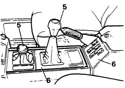
6. Remove the center console assembly.
7. Remove the sound insulation from the transmission tunnel.
8. Loosen the bolt and disconnect the upper part of the gearshift lever.
9. Loosen the screws securing the pressure plates
10. Drain the oil from the gearbox and transfer case (three plugs).
11. Clean the filter.
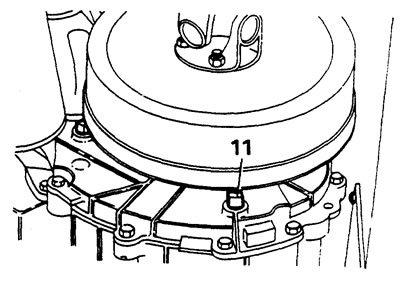
12. Disconnect the lambda probe wire, disconnect the intake pipes.
13. Disconnect the frame cross member.
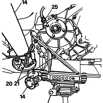
14. Mark the driveshaft flanges and disconnect from the transmission, hang to the side.
15. Disconnect the speedometer cable from the rear of the gearbox.
16. Disconnect the cable mount on the left side.
17. Unscrew the two bolts securing the clutch slave cylinder and remove the cylinder.
Removal the transmission assembly
18. Install a support stand in the area of the rear of the transmission block, support the transmission.
19. Unscrew the support cushion fasteners and remove the cushions.
20. Install the adapter onto the transmission stand.
21. Secure the adapter to the transmission.
22. Remove the support.
23. Lower the transmission to access the engine mounting bolts.
24. Disconnect the handbrake cable from the lever.
25. Disconnect the clip securing the cable sheath to the bracket and disconnect the cable.
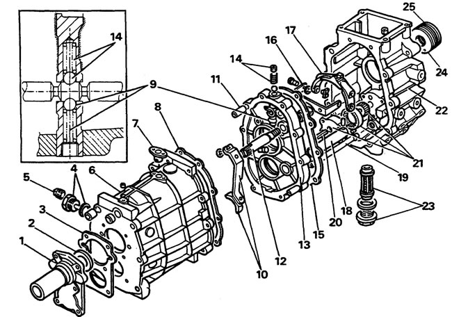
Gearbox housing components. 1 - front cover, 2 - input shaft seal, 3 - gasket, 4 - filler plug and washer, 5 - inspection plug, 6 - gearbox main body, 7 - lock, 8 - gasket, 9 - locking ball and spring, 10 - reverse gear lever and shoe, 11 - dowel pins, 12 - reverse gear rod, 13 - intermediate spacer, 14 - locking plug, ball and spring, 15 - gasket, 16 - fifth gear fork bracket, 17 - fifth gear engagement fork, 18 - reverse gear pinion shaft, 19 - oil line tube, 20 - oil pump drive shaft, 21 - oil pump gears and cover, 22 - fifth gear gear housing, 23 - drain plug and filter, 24 - bushing, 25 - gland
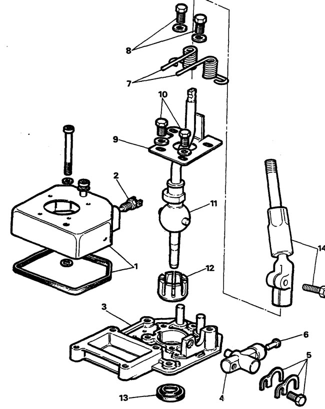
Components of the shift mechanism. 1 - upper part of the lever housing with a gasket, 2 - microswitch, 3 - lower part of the lever housing, 4 - reverse gear plunger, 5 - gaskets and bolt, 6 - microswitch plunger, 7 - springs, 8 - spring fixing bolts, 9 - limit plate, 10 - plate fixing bolts, 11 - shift lever, 12 - bushing, 13 - oil seal, 14 - upper part of the shift lever and mounting bolt.
26. Place the support under the engine.
27. Unscrew the transmission mounting bolts to the engine.
28. After making sure all bolts are removed, separate the transmission from the engine.
Separating the transfer case from the gearbox
29. Remove the transmission assembly from the lift.
30. Wrap the rope/cable around the transfer case.
31. Disconnect the transfer case lever and ventilation pipe.
32. Unscrew the bolts and two mounting nuts and separate the transfer case from the gearbox.
Connecting the gearbox and transfer case
1. Install the gearbox vertically with the clutch housing facing down on wooden blocks.
2. Lower the transfer case onto the gearbox. Tighten the bolts and nuts to a torque of 40 Nm.
3. Connect the tube and the transfer case lever.
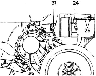
Adjusting the position of the transfer case lever
4. Make sure the transfer case lever is in neutral position.
5. Set the lever vertically, rotate the end of the rod until the holes in the rod align with the hole in the lever.
6. Install the pin and retaining ring, check the operation of the lever.
Installation
7. Install the adapter onto the stand, then the transmission unit onto the stand. Lubricate the mating surface of the clutch housing with sealant.
8. Engage any gear in the gearbox and transfer case to allow the input shaft to rotate. Make sure the clutch disc is installed correctly.
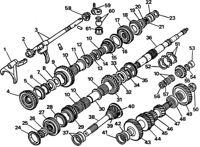
Gearbox components - gears and shafts. 1 - 3/4 gear fork and engagement rod, 2 - sleeve, 3 - 1/2 gear fork, 4 - 1/4 gear synchronizer, 5 - outer synchronizer ring, 6 - inner synchronizer ring, 7 - cone ring, 8 - washer, 9 - first gear pinion, 10 - needle bearings, 11 - sleeve, 12 - secondary shaft roller bearing, 13 - retaining ring, 14 - adjusting washer, 15 - fifth gear pinion, 16 - fifth gear synchronizer ring, 17 - fifth gear synchronizer sleeve, 18 - 5th gear synchronizer pressure plate, 19 - adjusting washer, 20 - retaining ring, 21 - sealing ring, 22 - oil seal housing, 23 - retaining ring, 24 - synchronizer ring 4th gear, 25 - tapered roller bearing, 26 - washer, 27 - 3/4 gear synchronizer sleeve, 28 - 3/4 gear synchronizer ring, 29 - third gear pinion, 30 - third gear sleeve, 31 - second gear pinion, 32 - washer, 33 - cone ring, 34 - outer synchronizer ring, 35 - inner synchronizer ring, 36 - secondary shaft, 37 - outer bearing race and adjusting washer, 38 - primary shaft, 39 - primary shaft bearing, 40 - fourth gear pinion, 41 - adjusting washer, 42 - roller bearing, 43 - intermediate shaft fourth gear pinion, 44 - intermediate shaft third gear pinion, 45 - intermediate shaft second gear pinion, 46 - 47 - intermediate shaft reverse gear pinion, 48 - roller bearing, 49 - intermediate shaft fifth gear pinion, 50 - fifth gear pinion retaining nut, 51 - retaining rings, 52 - second gear pinion and cone ring retaining spring ring, 53 - bushing, 54 - retaining ring, 55 - reverse idler pinion, 56 - washer, 57 - retaining ring, 58 - fifth gear pinion bushing, 59 - rod driver, 60 - shift lever ball and ring, 61 - nylon bushing
9. Place and lift the transmission unit coaxially with the engine, being careful not to pinch the tubes and wires.
10. Connect the transmission and engine. Tighten the fasteners to a torque of 40 N·m.
11. Reverse the procedures, tightening the threaded connections to specification and filling the transmission with the recommended oil.
Comments on this article