Contents: Assembly of synchronizers ⇩ Checking the clearances in the…⇩ Checking the axial clearances of the…⇩ Axial clearance of the second gear…⇩ Secondary shaft assembly ⇩ First gear components assembly ⇩ Intermediate shaft ⇩ Reverse gear shaft and pinion ⇩ Shift forks ⇩ Installing shafts and gears on an…⇩ Fifth gear fork ⇩ Fifth gear housing ⇩ Adjusting the intermediate shaft…⇩ Shift mechanism housing ⇩ Tightening torques for threaded…⇩ Homemade devices ⇩
Assembly of synchronizers
3/4 gear synchronizer
Note: All synchronizers have a similar design, except for the fifth gear synchronizer, which has a pressure plate.
1. Mark the completeness of each assembly.
2. Remove both snap rings from both sides of the synchronizer.
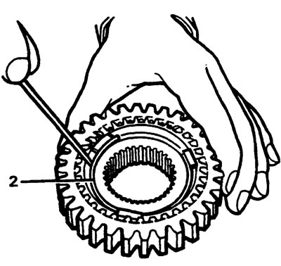
3. Remove the breadcrumbs and separate the rings.
4. Check all components for damage, including the spring rings for elasticity.
5. Check the sliding of the inner rings on the splines of the secondary shaft, (except for the fifth gear synchronizer).
6. Check the splines.
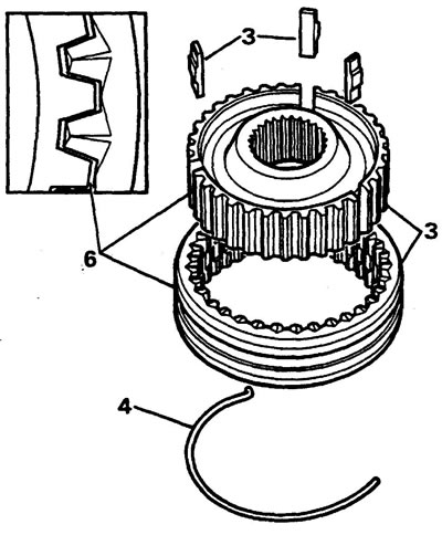
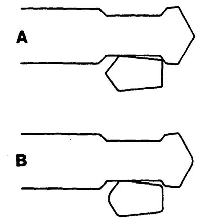
7. Check the condition of the synchronizer teeth.
Note: Fig. A shows teeth in good condition, Fig. B shows teeth in poor condition.
1/2 gear synchronizer
8. Repeat the procedures of points 1-6 as for the 3/4 gear synchronizer.
9. Check the external splines.
10. Check the condition of the teeth.
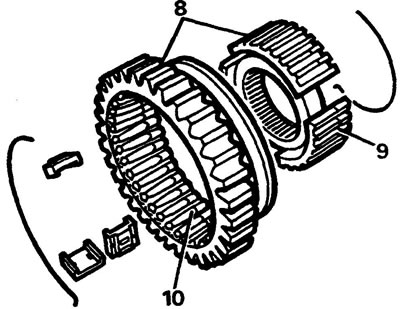
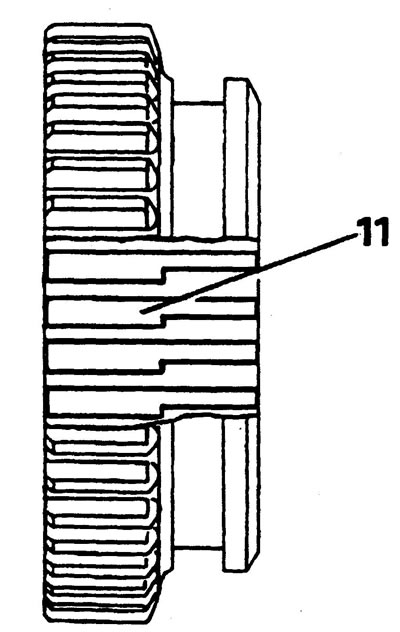
11. Install the inner part into the outer part so that the wide splines of the inner ring are towards the gear side (see picture).
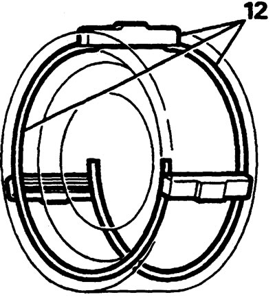
12. Install the crackers and secure them with the spring rings on each side of the synchronizer.
Note: The bent ends of the rings must be located in the same cracker, and the rings themselves must be directed in opposite directions.
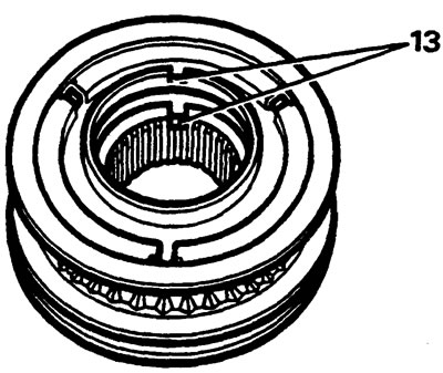
13. Assemble the 3/4 gear and 5th gear synchronizer as described in paragraph. 12.
Note: The fifth gear synchronizer pressure plate is mounted on the rear side of the synchronizer assembly with its groove opposite the groove of the inner synchronizer ring.
Checking the clearances in the synchronizer locking rings
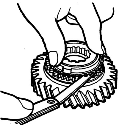
Check the clearance in each of the locking rings by pressing the ring towards the gear and using a flat feeler gauge. The gap must be at least 0.38 mm.
First gear pinion
Second gear pinion
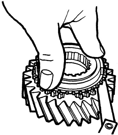
Third gear pinion
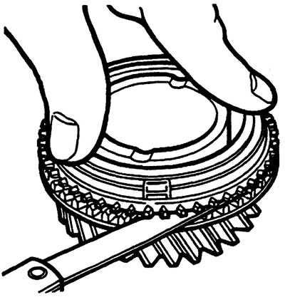
Fourth gear pinion

Fifth gear
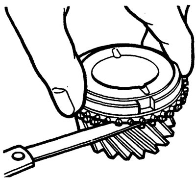
Primary shaft
1. Check the gear teeth and rings.
2. Grind the sliding surface of the oil seal if necessary.
3. Using special tools, remove the bearing guide.
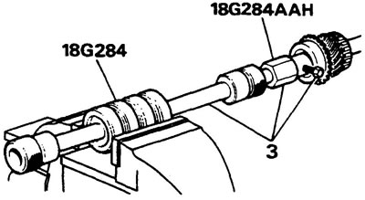
4. Using special tools, remove the bearing.
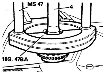
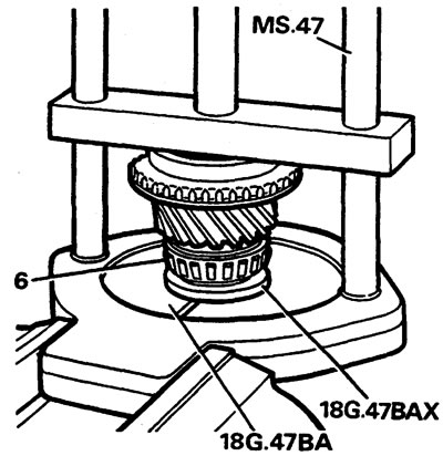
5. Install the new bearing guide.
6. Install the new bearing.
Secondary shaft
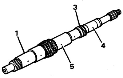
1. Check the shaft journals.
2. Check the condition of the grooves for the retaining rings.
3. Check the shaft teeth.
4.5. Blow out the shaft lubrication channels with compressed air, make sure that they are not clogged.
Checking the axial clearances of the secondary shaft components
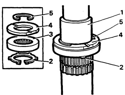
1. Clamp vertically in a vice.
2. Install the front 1/2 gear synchronizer snap ring.
3. Install the second gear cone ring.
4. Install the bushing.
5. Install the retaining ring.
Axial clearance of the second gear pinion
1. Install the needle bearing and second gear.
2. Install the third gear sleeve.
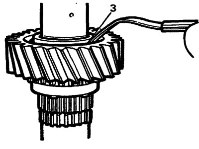
3. Check the clearance between the second gear and the hub flange. It should not be more than 0.2 mm.
4. Remove both components.
Axial clearance of third gear pinion
1. Install the needle bearing into the gear.
2. Install the sleeve into the gear.
3. Place the gear on a flat surface vertically along the axis, using a measuring block and feeler gauge, measure the gap between the edge of the gear and the block. It should not exceed 0.2 mm.
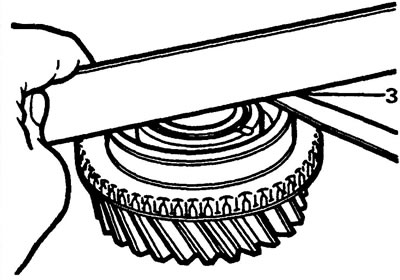
Axial clearance between the bearing and the adjusting sleeve of the first gear
1. Turn the shaft over.
2. Install the outer and inner locking rings of the second gear synchronizer.
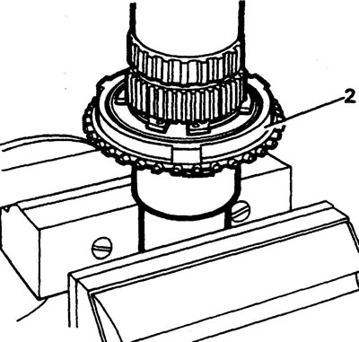
3. Install the 1/2 gear synchronizer housing with the fork groove facing up.
4. Install the retaining ring.
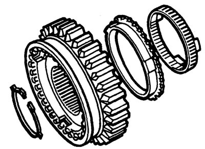
1/2 gear synchronizer assembly
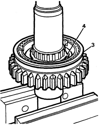
5. Install the first gear pinion, inner and outer locking rings.
6. Install the cone ring.
7. Install the spacer.
8. Install the bushing.
9. Install tool C.
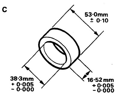
First gear bushing selection tool
10. Install the retaining ring.
11. Check the clearance between the bearing and the bushing. It should be within 0.75mm.
12. Remove the retaining ring, tool and bushing.
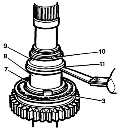
Adjusting bushings for first gear
| Catalog number | Thickness |
| FTC2005 | 30,905/30,955 |
| FTC2006 | 30,955/31,005 |
| FTC2007 | 31,005/31,055 |
| FTC2008 | 31,055/31,105 |
| FTC2009 | 31,105/31,155 |
Axial clearance between the sleeve and the first gear
1. Install the roller bearing and sleeve into the first gear.
2. Place the gear on the surface with the protrusion.
Note: The protrusion should be close in diameter to the bushing diameter so that the gear is suspended and does not rest on the plane.
3. Place the measuring block crosswise and measure the gap between the gear and the block. It should be no more than 0.2 mm.
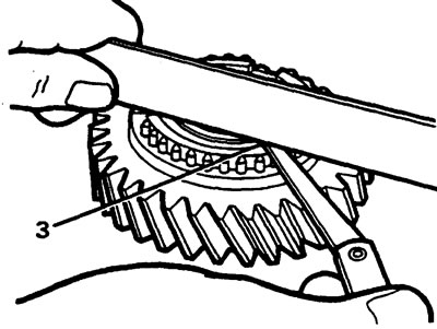
Secondary shaft assembly
1. Once the 1/2 synchronizer and spacer are installed, install the remaining components onto the rear end of the shaft.
2. Install the roller bearing and sleeve into the first gear.
3. Install the gear on the secondary shaft.
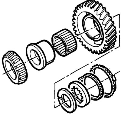
First gear components assembly
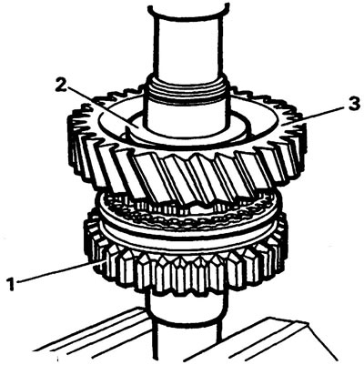
4. Install the tapered bearing onto the secondary shaft using a press and mandrels.
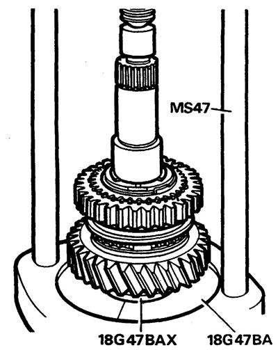
Caution: Make sure that the grooves in the locking ring are opposite the synchronizer crackers during pressing.
5. Turn the shaft over and press the assembly back against the retaining ring.
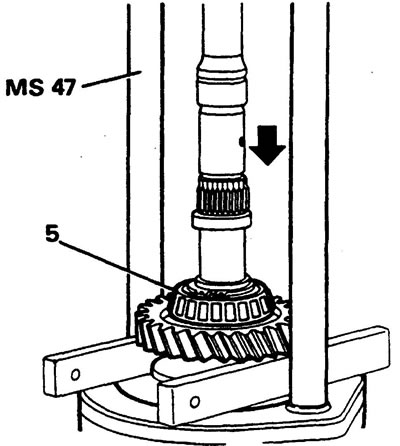
Note: This is necessary because it is possible that when pressing on, the bearing may clamp onto the sleeve, making it difficult to rotate.
6. Place the shaft horizontally in a vice and, using a screwdriver, check that the sleeve rotates freely.
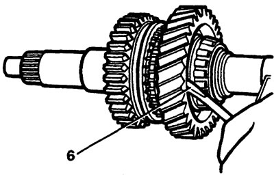
7. Place the secondary shaft vertically in a vice, with the rear end down, and install the second gear needle bearing and gear.
8. Install the third gear sleeve.
9. Install the third gear needle bearings.
10. Install the third gear gear.
11. Install the third gear synchronizer locking ring.
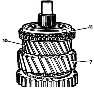
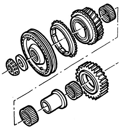
Installing a 3/4 gear synchronizer
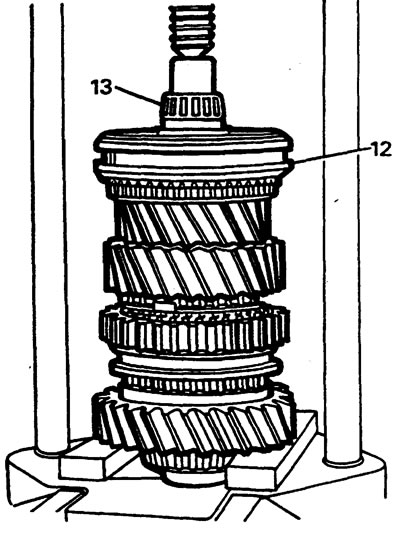
12. Install the 3/4 gear synchronizer sleeve.
13. Using a press and a support under the first gear, press the tapered roller bearing onto the shaft.
Intermediate shaft
1. Check the shaft for damage.
2. Press the bearings onto the intermediate shaft using a press and a stand.
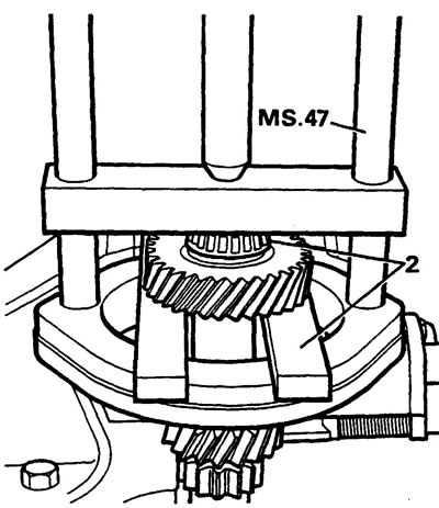
Reverse gear shaft and pinion
1. Remove one snap ring from the gear and take out the bearings.
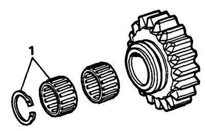
Note: The needles in the race of one of the bearings are not aligned with the horizontal axis. This is done for faster and smoother switching on. Replace bearings if necessary.
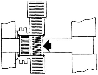
2. Install the bearings according to the figure and secure with retaining rings.
3. Check the condition of the idle gear and the teeth on the intermediate shaft and synchronizer ring.
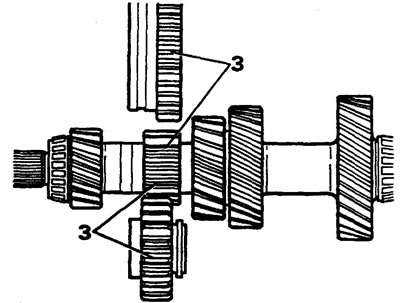
4. Check the idler shaft for damage..
Shift forks
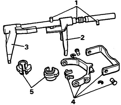
1. Check the fork stem and pins for damage and wear.
2. Check the 1/2 gear shift fork for damage and wear.
Note: The stem and fork are supplied as a set.
3. Check the 3/4 gear fork for damage and wear.
4. Check the 5th gear fork, 5th gear fork bracket and pins.
5. Check the condition of the bushings.
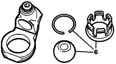
6. Remove the retaining ring and check the condition of the components.
Assembly of shift forks
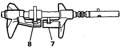
7. Install the 1/2 gear shift fork onto the rod as shown in the figure, the pin should be in the fork slot.
8. Install the sleeve and 3/4 gear fork according to the figure, the protrusion of the sleeve should be in the spline of the fork.
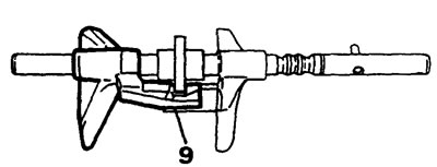
9. Slide the 3/4 gear sleeve and fork towards the 1/2 gear fork until the groove in the sleeve is positioned over the pin as shown.
Installing shafts and gears on an intermediate spacer
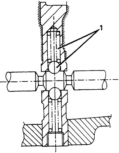
1. Place the spacer on the stand, secure it with bolts, install the bearing races, retaining spring and ball.
2. Check that both synchronizers are in neutral position and install the selector shaft assembly.
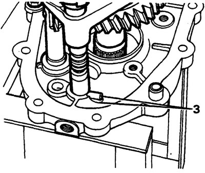
3. Install the secondary shaft and rod and forks on the spacer, orienting the pin as shown in the figure.
4. Install the intermediate shaft.
5. Rotate the fork stem and bushing to connect the reverse gear lever to the bushing flange.
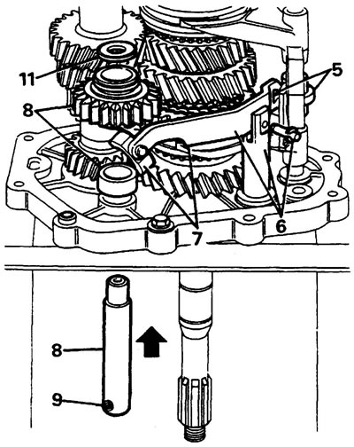
6. Install the reverse gear engagement lever into the groove of the rod and secure it with a pin and a retaining ring.
7. Install the shoe on the lever.
8. Install the reverse gear shaft, bushing and gear.
9. Place the shoe on the reverse gear and make sure that the shaft locking pin is located in the hole in the spacer housing.
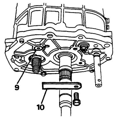
10. Secure the reverse gear shaft with plate "A" as shown in the figure.
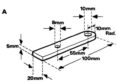
Dual-purpose device A. To prevent the shaft from falling out when the gearbox is turned over, and also to secure the fifth gear when tightening the nut. Use 5mm thick steel for the tool. When tightening the nut, use a suitable spacer with an outer diameter of 20mm, a length of 23mm, and an inner diameter of 8mm.
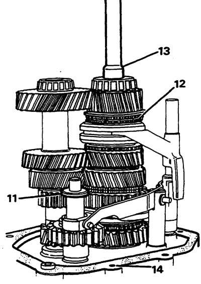
11. Install the washer on the shaft.
12. Install the fourth gear synchronizer ring.
13. Lubricate the pilot bearing and install the input shaft.
14. Install the gasket, having first unscrewed the spacer fixing bolts.
Installing the gearbox housing
1. Turn the shift fork shaft and sleeve to the neutral position see. drawing.
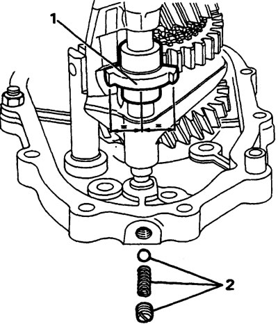
2. Install the locking ball, spring and plug.
3. Install the guide bushings.
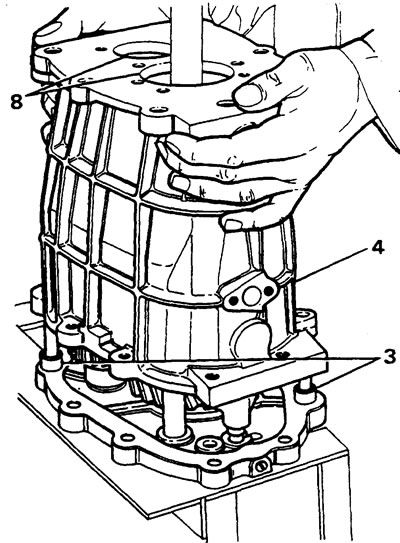
4. Carefully install the gearbox housing.
Note: Make sure the shift fork shaft aligns with the hole in the spacer.
5. Secure the spacer and gearbox housing to the stand using two M8x35 mm bolts.
6. Apply sealant to the joint surfaces and threaded holes and install the lock.
Caution: Do not use force when installing the lock. Rotate the housing or move the sleeve or shaft until the groove in the lock aligns with the projection on the sleeve.
7. Remove the locking ball plug, lubricate the threads with loctite 290, and screw it back in.
8. Install the intermediate and primary shaft collars.
Installing fifth gear gears.
Attention:
- when installing the fifth gear pinion on the intermediate shaft, the force when pressing the pinion should not be transmitted to the front bearing of the intermediate shaft.
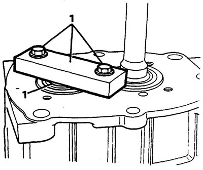
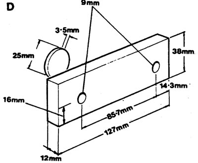
- It is necessary to make a "D" fixture and a thrust disc (see picture) to prevent damage to the bearing. The plate also holds the outer race of the input shaft bearing.
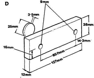
The "D" fixture is secured with two 8x25mm bolts and washers to the front of the gearbox.
1. Install the device and secure with bolts. Place the disc between the plate and the end of the intermediate shaft.
2. Turn the gearbox housing over.
3. Press the fifth gear onto the intermediate shaft using a special tool.
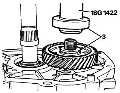
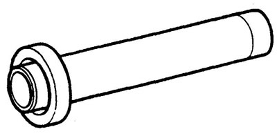
Device for installing/pressing secondary shaft seal.
4. Install the new lock nut, but do not tighten it.
5. Install the bearing, washer, gear and synchronizer ring onto the secondary shaft.
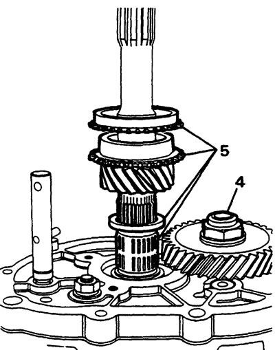
6. Press the fifth gear synchronizer assembly onto the secondary shaft using a special tool.
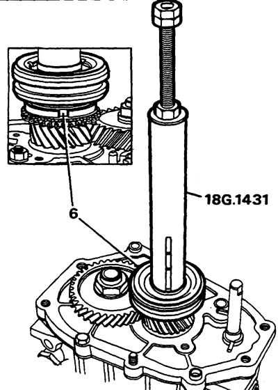
Caution: Before final pressing of the synchronizer, make sure that the protrusions are located in the grooves of the locking ring.
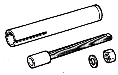
Device for installing fifth gear pinion and oil seal.
Note: the axial play of the fifth gear synchronizer hub should be within 0.005-0.055 mm, it is adjusted by selecting a washer of the required thickness.
| washer catalog number | thickness mm |
| FRC 5284 | 5,10 |
| FRC 5286 | 5,16 |
| FRC 5288 | 5,22 |
| FRC 5290 | 5,58 |
| FRC 5292 | 5,34 |
| FRC 5294 | 5,40 |
| FRC 5296 | 5,46 |
| FRC 5298 | 5,52 |
| FRC 5300 | 5,58 |
| FRC 5302 | 5,64 |
7. Install a washer of the required thickness and a retaining ring.
8. Measure the gap between the ring and the washer.
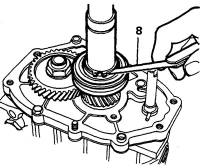
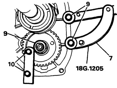
9. Tighten the lock nut using the LRT-51-003(18G 1205) lock nut.
Caution: To tighten the nut to the required torque of 218 Nm, you must use a tool with sufficient leverage.
10. Install tool "A" on the gearbox and, using a suitable tool, tighten the nut to a torque of 218 N·m.
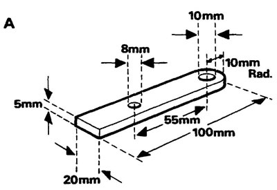
Device A for fixing the fifth gear when tightening the nut.
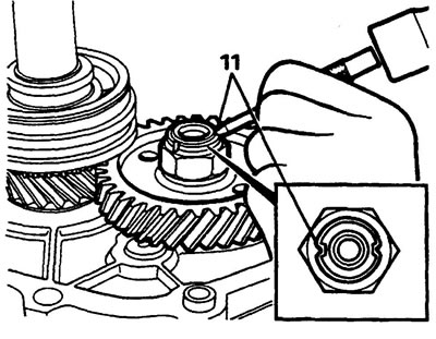
11. Using a punch, countersink the nut.
Fifth gear fork
1. Install the fifth gear fork bracket.
2. Install the bushing.
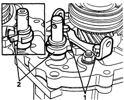
3. Install the shoes on the fork.
4. Install the fork onto the synchronizer sleeve and secure it with pins and retaining rings.
Note: Before installing the pins and rings, close the holes in the housing to prevent parts from falling into the gearbox.
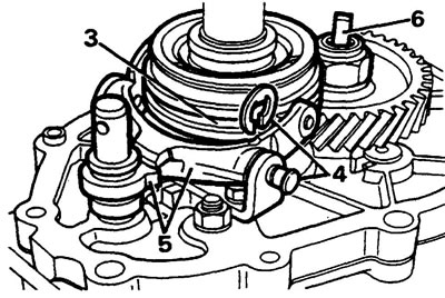
5. Insert the bushing pin into the fork.
6. Install the oil pump drive into the end of the intermediate shaft.
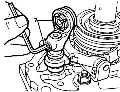
7. Install the rod leash and secure it with a screw, having previously lubricated the threads with Loctite.
Fifth gear housing
1. Install the gasket on the gearbox housing.
2. Install the fifth gear housing, aligning the oil pipe. Secure the body.
Note: When installing, do not apply excessive force, if it does not work the first time, turn the oil pump drive and try again.
Caution: To avoid damaging the rubber sealing ring during installation, wrap the secondary shaft splines with tape.
3. Install the rubber ring into the groove on the secondary shaft.
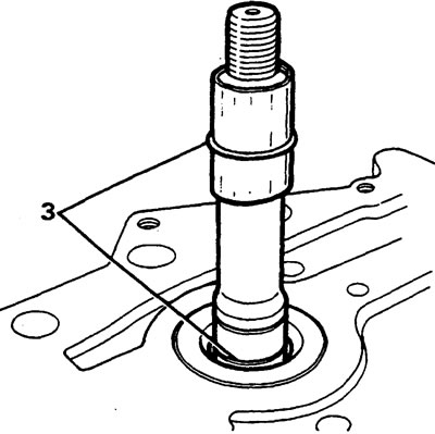
4. Install the seal cover on the secondary shaft using special tool LRT-37-015 (18G 1431).
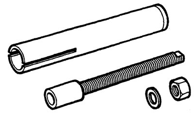
Device for installing fifth gear pinion and oil seal.
Adjusting the primary and secondary shaft bearings
1. Install the gearbox with the input shaft facing up.
Note: Correct washer selection is essential to ensure proper bearing operation.
2. Measure the thickness of the new front cover gasket.
3. Place the washer that was previously installed on the secondary shaft bearing race and hand tighten the mounting bolts.
4. Measure the gap between the front cover and the gearbox housing using two feeler gauges.
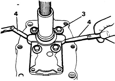
5. If necessary, replace the washer with another one so that the gap is 0.35-0.85 mm less than the thickness of the gasket.
Note: If the washer thickness is selected correctly, then after tightening the front cover mounting bolts to the specified torque, the axial clearance will be no more than 0.06 mm, and the primary and secondary shaft bearings will not be overtightened.
6. Remove the cover and the selected washer and gasket.
Secondary/primary shaft adjusting washers
| washer catalog number | washer thickness |
| FRC 4327 | 1,51 |
| FRC 4329 | 1,57 |
| FRC 4331 | 1,63 |
| FRC 4333 | 1,69 |
| FRC 4335 | 1,75 |
| FRC 4337 | 1,81 |
| FRC 4339 | 1,87 |
| FRC 4341 | 1,93 |
| FRC 4343 | 1,99 |
| FRC 4345 | 2,05 |
| FRC 4347 | 2,11 |
| FRC 4349 | 2,17 |
| FRC 4351 | 2,23 |
| FRC 4353 | 2,29 |
| FRC 4355 | 2,35 |
| FRC 4357 | 2,41 |
| FRC 4359 | 2,47 |
| FRC 4361 | 2,53 |
| FRC 4363 | 2,59 |
| FRC 4365 | 2,65 |
| FRC 4367 | 2,67 |
| FRC 4369 | 2,77 |
Adjusting the intermediate shaft bearings
1. Install the washer that was previously on the intermediate shaft bearing, install the front cover without the gasket, and hand tighten the bolts.
2. Measure the gap between the front cover and the gearbox housing using two feeler gauges. Select a shim to provide a clearance equivalent to the shim thickness that was selected and measured when adjusting the input and output shaft bearings.
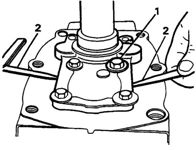
Note: If the washer thickness is selected correctly, then after tightening the front cover mounting bolts to the specified torque, the axial clearance will be no more than 0.025 mm.
3. Remove the cover and the selected washer and install the new oil seal with the open side facing the gearbox housing.
4. Install the selected washers and gasket.
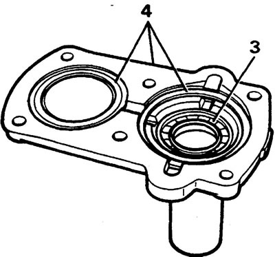
5. Wrap the input shaft splines with tape.
6. Lubricate the threads of the cover mounting bolts with adhesive.
Intermediate shaft adjusting washers
| catalog number | thickness, mm |
| FTC 0262 | 1,36 |
| FTC 0264 | 1,42 |
| FTC 0266 | 1,48 |
| FTC 0268 | 1,54 |
| FTC 0270 | 1,60 |
| FTC 0272 | 1,66 |
| FTC 0274 | 1,72 |
| FTC 0276 | 1,78 |
| FTC 0278 | 1,84 |
| FTC 0280 | 1,90 |
| FTC 0282 | 1,96 |
| FTC 0284 | 2,02 |
| FTC 0286 | 2,08 |
| FTC 0288 | 2,14 |
| FTC 0290 | 2,20 |
| FTC 0292 | 2,26 |
| FTC 0294 | 2,32 |
| FTC 0296 | 2,38 |
Shift mechanism housing
1. Remove the gearbox from the stand and place it on the workbench.
2. Install the shift mechanism gasket onto the gearbox housing.
Note: Make sure the end of the shift lever is positioned in the recess of the ball and the protrusion of the sleeve should be positioned on top of the fifth gear fork.
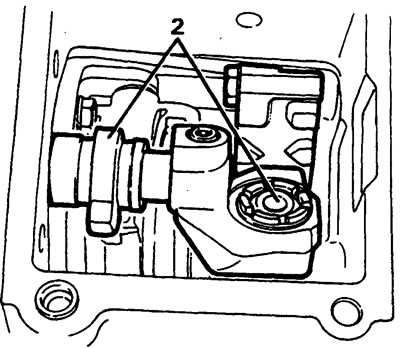
Installing the limit plate
1. Loosen the plate mounting bolts. Engage fourth gear and move the lever all the way to the right.
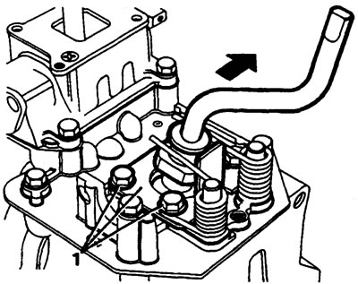
2. Tighten the plate mounting bolts.
3. Check that the adjustment is made correctly by engaging third gear, then fourth.
Installing the reverse gear plunger
1. Install the plunger and washers that were there earlier onto the shift mechanism housing.
2. Engage first gear and measure the clearance between the plunger and the lever flange.
Note: The gap should be within 0.60, 85mm, adjust by adding or decreasing the number of washers.
3. Install the reverse light switch plunger.
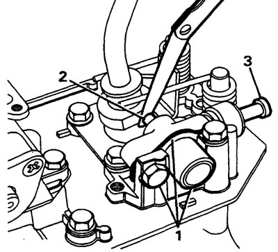
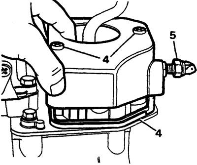
4. Install the rubber seal and cover.
5. Install the reverse light switch and adjust it (see electrical equipment section).
LT77 Transmission Specifications
- The gap between the reverse gear lever and the shoe is 0.725 mm
- Return plunger spring force: 45-55 kg
- The gap between the synchronizer locking rings and the gears is 0.38 mm
- Axial play of the fifth gear pinion is 0.020 mm
- Axial play of the third gear pinion is 0.020 mm
- Axial play of the second gear pinion is 0.020 mm
- Axial play of the first gear bushing is 0.7 mm
- Axial play of the first gear pinion is 20 mm
- Axial play of the fifth gear synchronizer hub is 0.005-0.055 mm
- The gap between the reverse gear plunger and the lever is 0.6-0.85 mm
Tightening torques for threaded connections Nm
- Oil pump mounting bolts - 8 Nm
- Fifth gear housing to gearbox housing - 25 Nm
- Clutch lever support pin to gearbox housing — 25 Nm
- Release bearing guide to gearbox housing mounting bolts — 25 Nm
- Slave cylinder to clutch housing mounting bolts - 25 Nm
- Front cover to gearbox housing mounting bolts — 25 Nm
- Fifth gear fork bracket mounting bolts - 25 Nm
- Clutch housing to gearbox housing mounting bolts — 70 Nm
- Oil drain plug - 50 Nm
- Oil drain plug with filter - 70 Nm
- Breather - 15 Nm
- Oil level plugs - 30 Nm
- The upper part of the gearshift lever to its lower part mounting bolt is 25 Nm
- Nuts securing the fifth gear to the intermediate shaft (after tightening, caulk) — 18 N·m
- Shift mechanism housing mounting bolts - 25 Nm
- Return plunger to the shift mechanism housing mounting bolts - 25 Nm
- Limit plate to gearshift mechanism housing mounting bolts - 25 Nm
- Clutch housing to cylinder block mounting bolts - 40 Nm
- Shift fork rod drive screw with internal hexagon - 25 Nm
- Reverse gear lever rod mounting nuts to housing — 25 Nm
- Threaded plug for fixing the locking ball and spring - 25 Nm
For other threaded connections, tightening torques are proportional to the diameter for:
| Metric connections, N·m | |
| M5 | 6 |
| Mb | 9 |
| M8 | 25 |
| M10 | 45 |
| M12 | 90 |
| M14 | 105 |
| M16 | 180 |
| Inch connections, N·m | |
| 1/4 | 9 |
| 5/16 | 24 |
| 3/8 | 39 |
| 7/16 | 78 |
| 1/2 | 90 |
| 5/8 | 136 |
Homemade devices
These devices must be made to avoid damage to gearbox parts during assembly or disassembly.
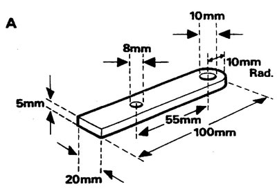
Device A has a dual purpose: to prevent the shaft from falling out when the gearbox is turned over, and also to fix the fifth gear when tightening the nut. Use 5mm thick steel for the tool. When tightening the nut, use a suitable spacer with an outer diameter of 20mm, a length of 23mm, and an inner diameter of 8mm.
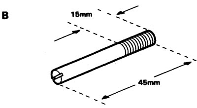
Four threaded (8 mm) pins for fixing the gearbox housing on the stand (fixture E).
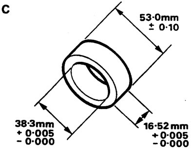
Steel device for selecting the first gear bushing.
Tool "D" and thrust disc for fixing the intermediate shaft and preventing damage to the bearing. The "D" fixture is secured with two 8x25mm bolts and washers to the front of the gearbox.
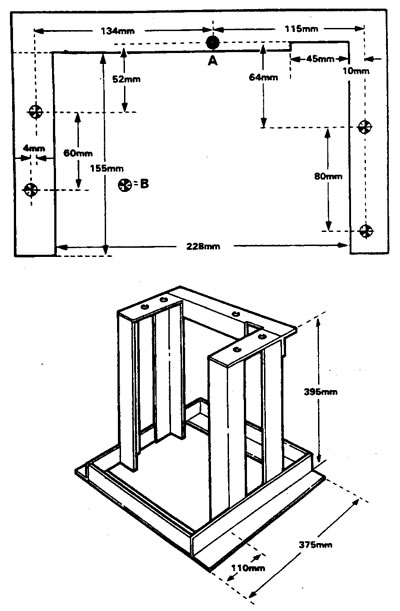
Gearbox disassembly/assembly stand. Made from 30x30 mm steel angle. Hole A is drilled through with a 10 mm drill bit. Places marked as B should not be drilled through, but only recesses should be made with the same drill to install the threaded pins.
Special tool
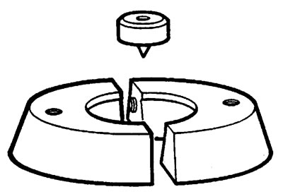
LRT-37-001 Intermediate shaft bearing puller adapter. 18S.47VA
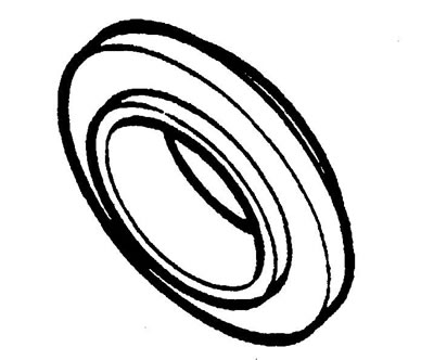
LRT-37-002 Device for primary shaft bearing puller. 18C.47VAH.
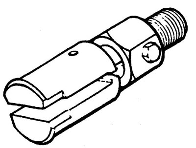
LRT-37-004 Input shaft bearing sleeve puller adapter. 18C.284AAN.

LRT-37-009 Bearing Inner Race Removal Tool - Main Part.186.705
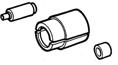
LRT-37-010 Adapter for removing the sliding sleeve of the intermediate shaft fifth gear oil seal. 18G.705-1A.
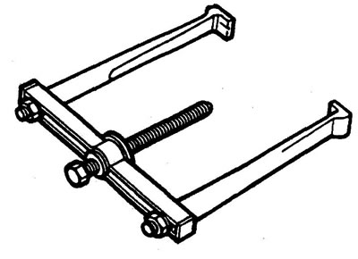
LRT-37-012 First Gear Synchronizer Hub Puller.18G.1400
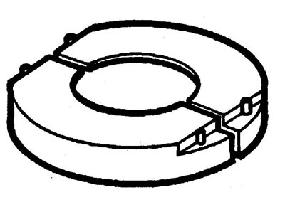
LRT-37-013 Adapter for fifth gear puller.18G.14001
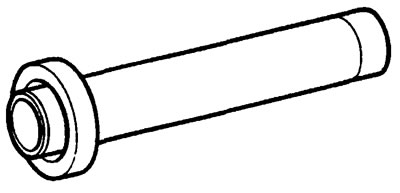
LRT-37-014 Secondary shaft rear oil seal puller.18G.1422
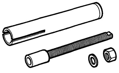
LRT-37-015 Secondary shaft seal retainer and fifth gear synchronizer installation tool.18G.1431
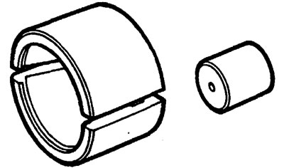
LRT-37-017 Intermediate shaft bearing puller.18G.705-7
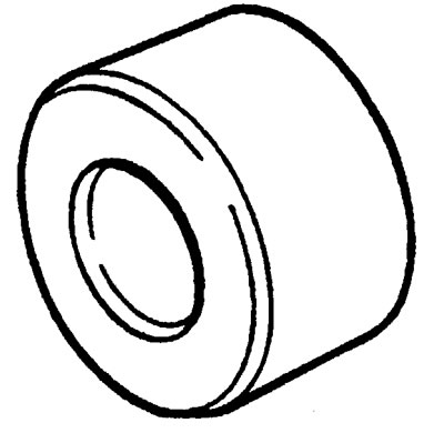
LRT-37-018 Bearing Simulator
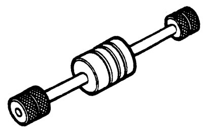
LRT-99-004 Impact Puller.18G.284
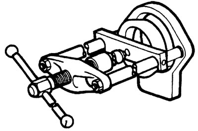
LRT-99-002 Manual npecc.MS.47
Comments on this article