Contents: Checking the axial clearance of the…⇩ Installation of secondary and…⇩ Installing 5th and reverse gears ⇩ Rear housing installation - gearbox…⇩ Rear housing installation - Type C…⇩ Rear housing installation - Type D…⇩ Installing the leash - gearbox type A ⇩ Installation of the leash - gearbox…⇩ Installing the shift rod housing -…⇩ Installing the transfer case shift…⇩ Installing the shift mechanism -…⇩ Installing the shift mechanism -…⇩ Installing the shift rod housing -…⇩ Installing the shift rod housing -…⇩ Adjusting the 5th gear limit screw -…⇩ Adjusting the lever retaining spring…⇩ Adjusting the lever retaining spring…⇩ Adjusting the lever retaining spring…⇩ Clutch housing installation - Type A…⇩ Installing the clutch housing - Type…⇩ Clutch housing installation - Type C…⇩ Installing the adapter - gearbox…⇩
Checking the axial clearance of the secondary and intermediate shafts
Note: The secondary and intermediate shaft axial clearance must be assessed prior to gearbox assembly. This assessment is performed with the shafts temporarily installed in the intermediate plate and main crankcase. Take measurements using a digital indicator.
Installation axial clearance: 0.01 - 0.06 mm
Adjusting washers are installed under the bearing raceways in the intermediate plate.
1. Install the bearing races into the front cover of the main crankcase.
2. Install the front cover without the oil seal.
3. Clamp the main boat in a vice with the front cover facing down.
4. Install the input shaft without the 4th gear synchronizer locking ring.
5. Install the secondary shaft onto the primary shaft (without gears).
6. Install the adjusting washer and secondary shaft bearing race into the intermediate plate.
7. Install the intermediate plate and tighten the eight mounting bolts.
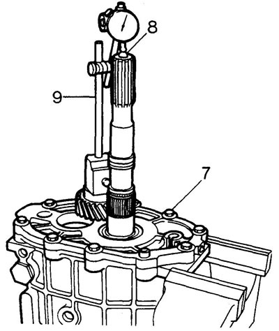
8. Place a steel ball of suitable diameter into the centering hole of the secondary shaft.
9. Install the indicator stand as shown in the figure.
10. Rotate the secondary shaft to seat the bearings. Reset the indicator to zero.
11. Raise the secondary shaft and read the indicator readings.
12. If the axial clearance is outside the permissible limits, install an adjusting washer of the required thickness.
13. After installing the new washer, repeat the clearance checking procedure.
14. Remove the secondary shaft and adjust the axial clearance of the intermediate shaft in a similar manner.
15. Disassemble the unit and prepare for assembly.
Installation of secondary and intermediate shafts in the intermediate plate
1. Secure the intermediate plate to the assembly stand.
2. Install the previously selected adjusting washers and bearing races into the plate.
3. Install the inner ball and retainer spring into the intermediate plate. To temporarily secure the spring and ball, install a rubber plug.
4. Move both synchronizers to neutral position and install the shift rod and forks into their couplings.
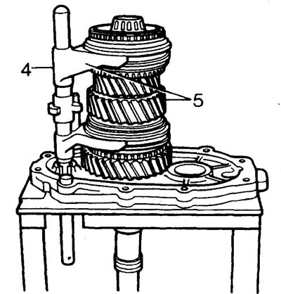
5. Install the secondary shaft, rod and shift forks as an assembly into the intermediate plate. Insert the rod pin into the slot in the plate.
6. Install the 4th gear synchronizer locking ring.
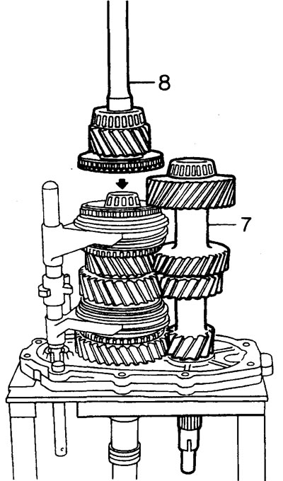
7. Install the intermediate shaft by lifting the secondary shaft to clear the intermediate shaft rear bearing.
8. Lubricate the secondary shaft support bearing and install the primary shaft.
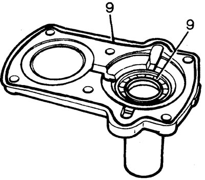
9. Install the oil seal into the front cover until it stops. Apply to the front cover flange as shown in the figure.
Note: On early models the seal did not have a wax coating. Lubricate the sealing lip with transmission oil. On later models the seal is wax coated. Install dry.
10. Install the bearing races and retaining rings into the main crankcase. Install the front cover.
11. Apply Hylosil RTV 102 sealant to the mating surface of the intermediate plate and install the main crankcase.
12. Tighten two or three technological bolts securing the intermediate plate to the main crankcase.
13. Place a new sealing ring on the locking sleeve holder and install the holder.
14. Remove the assembly from the assembly stand and secure it in a vice.
Installing 5th and reverse gears
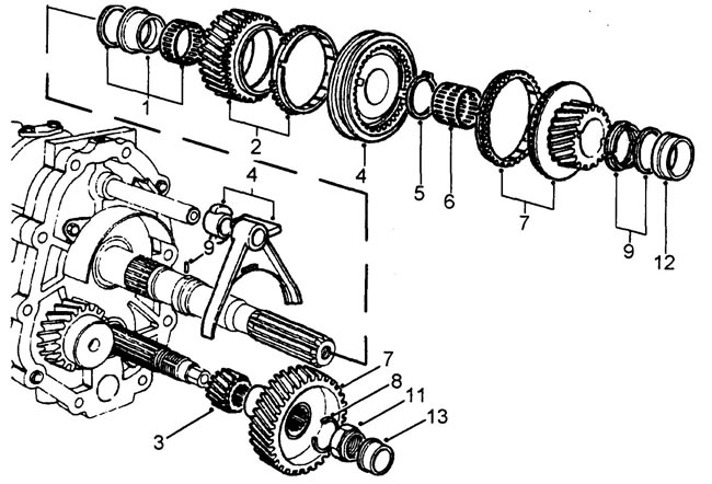
1. Install the selected reverse gear adjusting washer, bushing and needle bearing onto the secondary shaft.
2. Install the reverse gear and synchronizer locking rings on the secondary shaft.
3. Install the reverse gear on the intermediate shaft
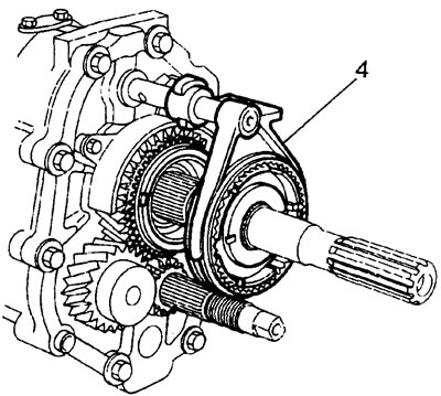
4. Assemble the locking sleeve, 5th gear/reverse shift fork and synchronizer hub separately. Install the assembled parts onto the secondary shaft splines and gear shift rod. Make sure that the locking ring is correctly installed in the synchronizer hub.
5. Install the new retaining ring.
Note: Check the axial clearance of the reverse gear. If necessary, adjust it by replacing the adjusting washer. The gap should be within 0.005 - 0.055 mm.
6. Install the 5th gear needle bearing.
7. Install the 5th gear and synchronizer locking rings on the secondary shaft. Install the 5th gear on the intermediate shaft.
8. Late models: Install the 5th gear retaining ring on the intermediate shaft.
Note: The beveled end of the washer must face the gear.
9. Install a new thrust spacer on the secondary shaft. Install the thrust segments and retaining ring.
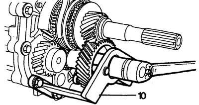
10. Holding the 5th gear gear of the intermediate shaft with the LRT-37-023 tool, tighten the gear mounting nut to a torque of 220 N·m.
11. Stake the nut skirt
12. Using mandrels LRT-37-015 and LRT-37-021, press the rear bearing race onto the secondary shaft spacer.
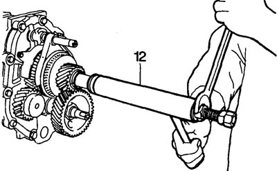
13. Heat the intermediate shaft bearing slightly and install it on the shaft.
14. Remove the rubber plug and install the outer spring and the piston rod retainer ball into the intermediate plate.
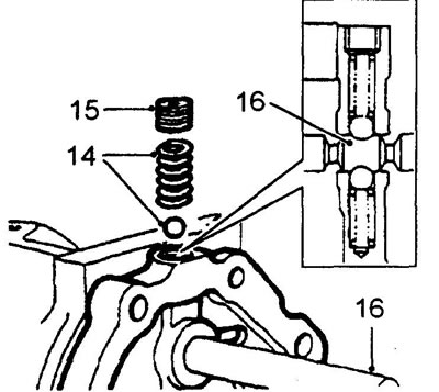
15. Tighten the locking plug to 25 Nm.
16. By moving the rod, make sure that the lock operates correctly
Rear housing installation - gearbox types A and B
1. Unscrew the technological bolts securing the intermediate plate to the main crankcase.
2. Install the oil filter.
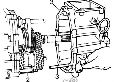
3. Apply Hylosil RTV 102 sealant to the mating surfaces of the main and rear crankcases, install the rear crankcase. Make sure the rear crankcase tube enters the filter and the oil pump drive engages.
Caution: Do not use force when installing the rear crankcase. Adjust the position of the oil pump drive if necessary.
4. Tighten the rear crankcase, intermediate plate and main crankcase mounting bolts.
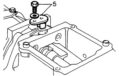
5. Apply Hylosil RTV 102 sealant to the mating surface of the locking sleeve holder, install the holder and tighten the mounting bolts to a torque of 8 Nm.
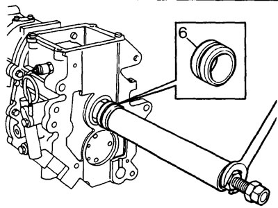
6. Using mandrels LRT-37-015 and LRT-37-21, install the secondary shaft seal spacer.
Rear housing installation - Type C gearbox
1. Lubricate the new shift rod seal with transmission oil.
2. Install the oil seal.
3. Install the oil filter.
4. Apply Hylosil RTV 102 sealant to the mating surfaces of the main and rear crankcases.
5. Install the rear crankcase. Make sure the rear crankcase tube enters the filter and the oil pump drive engages.
Caution: Do not use force when installing the rear crankcase. Adjust the position of the oil pump drive if necessary.
6. Tighten the rear crankcase mounting bolts in a diagonal sequence to 25 Nm.
7. Install the spacer.
8. Install the speedometer drive pinion onto the secondary shaft splines.
9. Using a drift, carefully tap the speedometer drive pinion into place.
10. Lubricate the new speedometer drive housing sealing ring with transmission oil.
11. Lubricate the speedometer drive gear with silicone grease.
12. Install the speedometer drive by engaging the drive and driven gears.
13. Apply Hylosil RTV 102 sealant to the mating surface of the locking sleeve holder, install the holder and tighten the mounting bolts to a torque of 8 Nm.
14. Install the pin on the shift rod and tighten the mounting nut.
15. Install the propeller shaft mounting flange onto the secondary shaft.
16. Install the new sealing ring and spacer.
17. Install a new lock washer.
18. Tighten the flange mounting bolt to 90 Nm.
19. Bend the tabs of the lock washer onto the edge of the bolt.
Rear housing installation - Type D gearbox
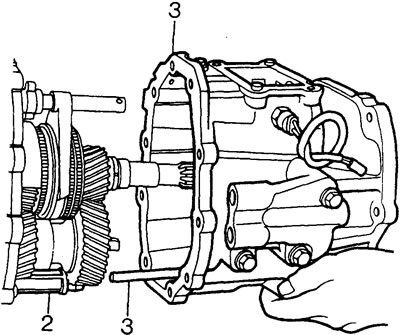
1. Unscrew the technological bolts securing the intermediate plate to the main crankcase.
2. Install the oil filter.
3. Apply Hylosil RTV 102 sealant to the mating surfaces of the main and rear crankcases, install the rear crankcase. Make sure the rear crankcase tube enters the filter and the bearings are installed.
Caution: Do not use force when installing the rear crankcase. Adjust the position of the oil pump drive if necessary.
4. Tighten the rear crankcase, intermediate plate and main crankcase mounting bolts.
5. Apply Hylosil RTV 102 sealant to the mating surface of the locking sleeve holder, install the holder and tighten the mounting bolts to a torque of 8 Nm.
Installing the leash - gearbox type A
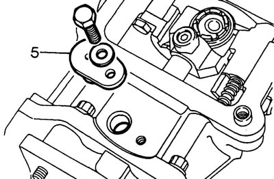
1. Install the leash onto the shift rod.
2. Apply Loctite 270 locking adhesive to the threads of the new retaining screw. Tighten the screw to a torque of 25 N·m.
Note: The screw must go into the hole in the rod.
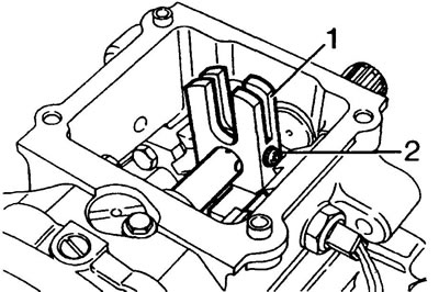
3. Move the shift rod to neutral position.
Installation of the leash - gearbox type B and D
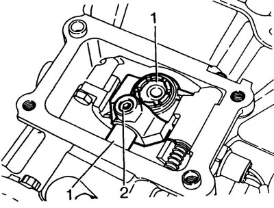
1. Install the leash onto the shift rod. The ball of the driver must point towards the secondary shaft 2. Apply Loctite 270 locking adhesive to the threads of the new locking screw. Tighten the screw to a torque of 25 N·m.
Note: The screw must go into the hole in the rod.
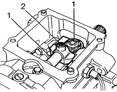
Gearbox type B
Gearbox type D
Installing the shift rod housing - Type A gearbox
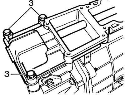
1. Apply Hylosil RTV 102 sealant to the mating surface of the piston rod housing. Install the piston rod housing onto the rear crankcase.
2. Check for engagement of the rollers and the shift rod linkage.
3. Tighten the three mounting bolts shown in the figure.
Installing the transfer case shift housing - Type A gearbox
1. Lubricate the body gasket with grease and place it on the piston rod body.
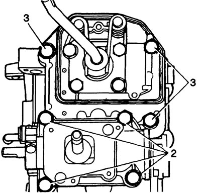
2. Install the transfer case shift housing onto the gearbox shift mechanism rod housings
3. Hand tighten the four mounting bolts.
Installing the shift mechanism - Type A gearbox
1. Lubricate the body gasket with grease and place it on the piston rod body.
2. Install the shift mechanism onto the gearshift rod housings. Check that the ball joint of the lever is seated correctly in the seat
3. Hand tighten the four mounting bolts.
4. Tighten the gearbox and transfer case shift mechanism mounting bolts to a torque of 25 Nm.
Installing the transfer case shift housing - Type B gearbox
1. Lubricate the housing gasket with grease and place it on the main crankcase.
2. Install the transfer case shift housing. Tighten the four mounting bolts to 25 Nm.
Installing the shift mechanism - Type B gearbox
1. Apply Hylosil RTV 102 sealant to the mating surface of the rear crankcase.
2. Install the switching mechanism. The shift lever should pass through the center of the linkage and engage with the lever guide.
3. Tighten the mounting bolts to 25 Nm.
Installing the shift rod housing - Type C gearbox
1. Lubricate the rod driver with lithium based grease.
2. Install the rod housing onto the rear crankcase, engage the rod pin and the leash.
3. Install the bolts, washers and piston rod housing support cushions into the rear crankcase and tighten the fasteners by hand.
4. Install the bolts, washers and piston rod housing bracket support pads into the rear crankcase and tighten the fasteners by hand.
5. Tighten all bolts to 50 Nm.
Installing the shift rod housing - Type D gearbox
1. Apply Hylosil RTV 102 sealant to the mating surface of the rear crankcase.
2. Install the rod housing onto the rear crankcase, engage the ball joint of the lever with the seat.
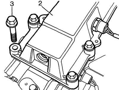
3. Tighten the mounting bolts to 25 Nm.
Adjusting the 5th gear limit screw - Type A gearbox
1. Engage reverse gear. Apply a slight force on the lever, directed forward and to the left, and tighten the limit screw until it contacts the leash.
2. Loosen the screw until there is 25 mm of free play on the shift lever (along the lever handle). Check the reliability of 5th gear engagement.
3. Tighten the screw lock nut.
4. Check that all gears are engaged securely.
Adjusting the lever retaining spring - type A gearbox
Note: The purpose of this adjustment is to create equal spring force on the shift lever pins when the lever is positioned in the 3rd and 4th gear engagement range. This means that when the transmission is shifted into neutral, the shift lever automatically positions itself in the 3rd and 4th gear engagement range.
1. Engage 3rd or 4th gear.
2. Turn the retaining spring adjusting screws so that both ends of the spring move away from the lever pins by approximately 0.5 mm.
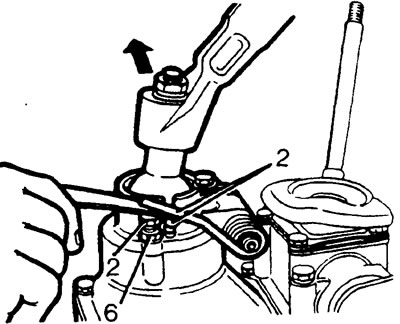
3. Apply a slight force to the left on the lever and turn the right adjusting screw until the right end of the spring touches the lever pin.
4. Change the direction of force application and repeat the adjustment operation for the left end of the spring.
5. Turn the screws to lower both ends of the spring an equal distance so that the lever just begins to feel a radial movement.
6. Tighten the locknuts of the adjusting screws.
7. Shift the gearbox into neutral and pump the lever several times: it should automatically return to the 3/4 gear engagement zone.
Adjusting the lever retaining spring - type B gearbox
1. Loosen the adjusting plate mounting bolts. Engage fourth gear and move the lever all the way to the right.
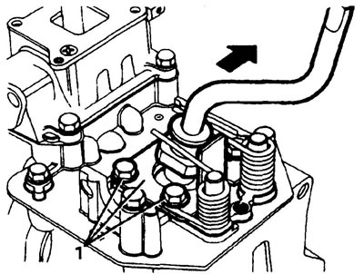
2. Tighten the adjusting plate bolts.
3. Check the adjustment by sequentially engaging 3rd and 4th gears.
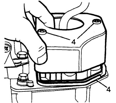
4. Install the rubber gasket on the shift mechanism housing, install the cover and tighten the mounting screws. Apply locking adhesive to the screw threads.
Adjusting the lever retaining spring - type C gearbox
Note: The purpose of the adjustment is to ensure that the gearshift lever automatically moves to the 3rd and 4th gear engagement zone when the gearbox is in neutral.
1. Turn the retaining spring adjusting screws so that both ends of the spring move away from the lever pins by approximately 0.05 mm.
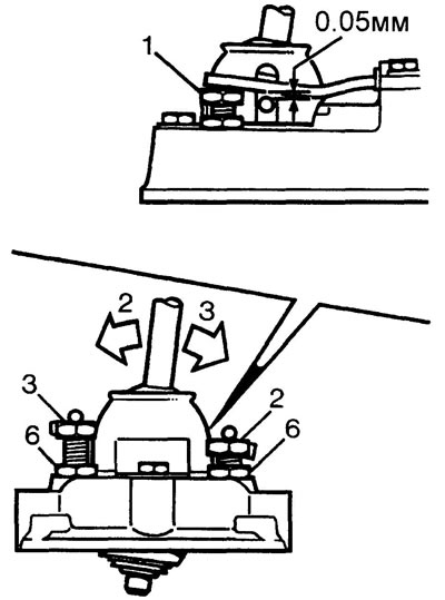
2. Apply a slight force to the left on the lever and turn the right adjusting screw until the right end of the spring touches the lever pin.
3. Change the direction of force application and repeat the adjustment operation for the left end of the spring.
4. Shift the gearbox into neutral and pump the lever several times: it should automatically return to the 3/4 gear engagement zone.
5. Tighten the locknuts of the adjusting screws.
Clutch housing installation - Type A gearbox
1. Install the clutch housing onto the gearbox using the guide pins.
2. Install the mounting bolts.
Note: 45mm long bolts fit through the guide pin holes.
3. Tighten the bolts in a diagonal sequence to a torque of 72 N·m.
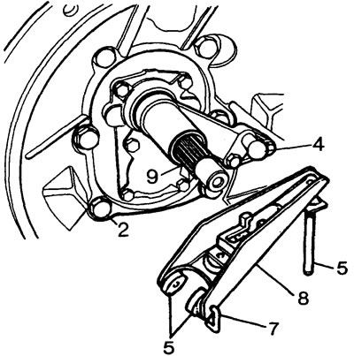
4. Install the release bearing guide and tighten the mounting bolts.
5. Lubricate the contact surfaces of the guide and release fork with lithium-based grease.
6. Install the release bearing drive linings and the release bearing onto the fork.
7. Secure the release bearing to the fork with new clips.
8. Install the fork and release bearing.
9. Lubricate the input shaft splines with lithium based grease.
Note: 45mm long bolts fit through the guide pin holes.
Installing the clutch housing - Type B gearbox
1. Install the clutch housing onto the gearbox using the guide pins.
2. Install the mounting bolts.
3. Tighten the bolts in a diagonal sequence to a torque of 72 N·m.
(The original text was published on the website: www.LRman.ru)
4. Lubricate the release bearing guide, release fork, axle and push rod with lithium-based grease.
5. Install a new retaining ring on the fork support in the guide, install the guide.
6. Install the clip on the fork and tighten the clip mounting bolt by hand.
7. Install the fork on the guide so that the fork clip is located behind the retaining ring. Tighten the clip mounting bolt.
8. Install the release bearing and secure it with clips to the fork.
Clutch housing installation - Type C gearbox
1. Install the clutch housing onto the gearbox using the guide pins.
2. Install the mounting bolts.
Note: The longest bolts are installed in the guide pin holes.
3. Tighten the bolts in a diagonal sequence to a torque of 72 N·m.
4. Lubricate the contact surfaces of the guide and release fork with lithium-based grease.
5. Install the fork and release bearing.
Installing the adapter - gearbox type D
1. Install the adapter onto the gearbox using the guide pins.
2. Install the mounting bolts.
Note: The longest bolts are installed in the guide pin holes.
3. Tighten the bolts in a diagonal sequence to a torque of 72 N·m.
4. Lubricate the clutch release fork bearings with lithium-based grease.
5. Install the release bearing guide and tighten the two mounting bolts.
Comments on this article