Contents: Installing a transfer case ⇩ Installing the gearbox on the engine ⇩ Gearbox holder LRT 99-008A ⇩
Caution: For safe operation, we recommend using a special gearbox puller/holder. A drawing of the holder is provided at the end of this section.
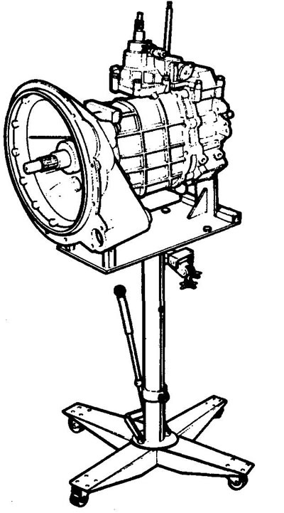
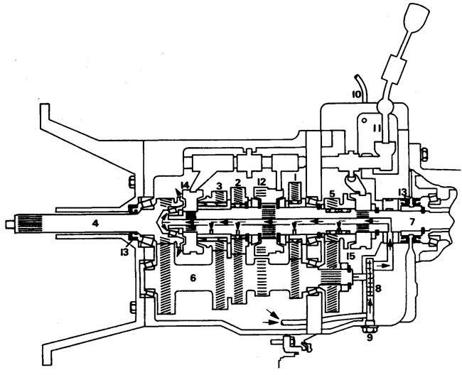
1 - 1st gear pinion of secondary shaft, 2 - 2nd gear pinion of secondary shaft, 3 - 3rd gear pinion of secondary shaft, 4 - primary shaft, 5 - 5th gear pinion of secondary shaft, 6 - intermediate shaft, 7 secondary shaft, 8 - oil pump, 9 - drain plug, 10 - ventilation tube, 11 - gear shift crossmember, 12 - 1/2 gear synchronizer, 13 - oil seal, 14 - 3/4 gear synchronizer, 15 - 5th gear synchronizer.
1. Place the car on a lift.
2. Disconnect the battery.
3. Remove the center console, see. "Body".
4. Remove the sound insulation from the driveshaft tunnel.
5. Loosen the bolt and remove the upper gear shift lever.
6. Unscrew the seven screws securing the gearshift lever and transfer case cover.
7. Remove the traction control arm retaining rings.
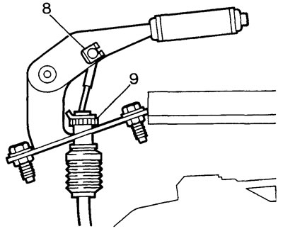
8. Remove the cotter pin and the shackle of the parking brake cable.
9. Remove the C-ring and cable adjustment assembly.
10. Move the transfer case lever to the downshift position to prevent the lever from falling into the tunnel when removing the gearbox.
11. Unscrew the bolt securing the gearbox ventilation tube to the engine block.
12. Unscrew the bolts securing the fan diffuser to the radiator.
13. Place the diffuser on the fan blades.
14. Raise the car
15. Drain the oil from both boxes.
16. Remove the exhaust pipes.
17. Disconnect the intermediate hanger of the exhaust pipe and move the pipe to the side.
18. Loosen the clutch slave cylinder mounting bolts.
19. Remove the hydraulic cylinder and spacers from the clutch housing.
20. Mark the relative positions of the driveshaft mounting flanges.
21. Disconnect the front and rear propeller shafts from the transfer case.
22. Disconnect the speedometer cable from the transfer case.
23. Disconnect the parking brake cable from the propeller shaft tunnel.
24. Temporarily secure the gearbox to the frame crossmember for subsequent installation of the LRT 99-008A holder (see drawing).
25. Unscrew the bolts and nuts securing the gearbox crossmember to the frame.
26. Unscrew the crossmember fasteners to the gearbox support.
27. Remove the cross member.
28. To achieve gearbox balancing on the jack, install the holder so that point A is located above the jack lifting frame. Drill the holes for mounting the B holder on the jack frame on site. Secure the gearbox at points C using the lower transfer case rear cover mounting bolts. Raise the jack until it supports the weight of the gearbox, remove the temporary support.
29. Lower the jack until the transfer case lever comes out of the tunnel.
30. Disconnect the differential lock switch connector.
31. Disconnect the reverse light switch connectors.
32. Disconnect the ventilation tubes from the wiring of the boxes.
33. Place a temporary support under the engine sump (place wooden blocks between the pallet and the support).
34. Loosen the clutch housing mounting nuts.
35. Remove the gearbox from the vehicle.
36. Remove the gearbox from the holder and place it on the workbench.
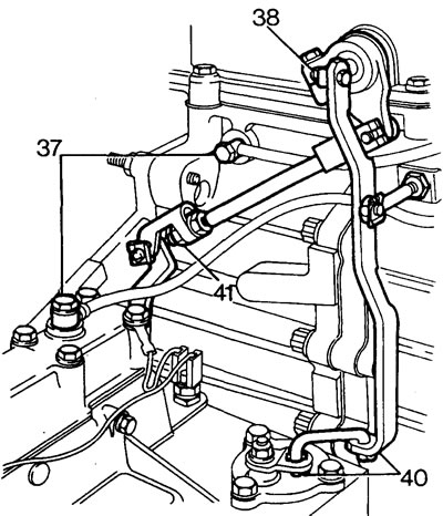
37. Disconnect the ventilation tubes and discard the sealing washers.
38. Loosen the nut and remove the bolt securing the transfer case gear shift lever.
39. Assemble the spacers and washers.
40. Remove the two retaining rings and the differential lock lever rod.
41. Unscrew the lower nut of the transfer case gear shift lever control rod.
42. Attach a cable to the transfer case and hang it on the lift.
43. Unscrew the nut and five bolts securing the transfer case.
44. Remove the transfer case.
Installing a transfer case
9. Clean the mating surfaces of both boxes.
10, Check that the upper guide pin is installed correctly. Install the transfer case.
11. Tighten the bolts and mounting nut to 34 Nm.
12. Connect the shift lever control rod.
13. Install the differential lock lever rod and secure the rod with two retaining rings.
14. Connect the control rod to the shaft, tighten the nut to a torque of 2 Nm.
15. Install the ventilation tubes, tighten the mounting nuts to a torque of 15 N·m.
Installing the gearbox on the engine
16. Install the gearbox on the holder.
17. Wipe the mating surfaces of the clutch housing and gearbox.
18. Wipe the gearbox input shaft and lubricate with NLG52 grease.
19. Temporarily install the gear shift lever and engage any gear to facilitate the entry of the input shaft into the clutch disc.
20. Move the gearbox to the installation position.
21. Install the gearbox on the engine and tighten the mounting nuts. Place a temporary support under the box.
22. Disconnect the holder, apply Loctite 290 locking adhesive to the two removed bolts, and reinstall the bolts.
23. Reinstall the removed parts.
Gearbox holder LRT 99-008A
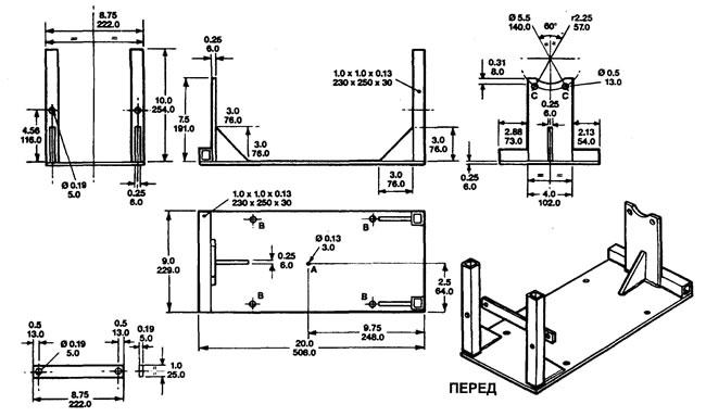
Upper dimensions in inches, lower dimensions in mm. Material - rolled steel, arc electric welding.
Comments on this article