Contents: Dismantling ⇩ Installation ⇩
Dismantling
1. Disconnect the negative battery terminal.
2. Remove the hydraulic support.
ENGINE - MODIFICATION K, volume 1.8, Front exhaust camshaft oil seal, Right engine hydraulic support.
3. Remove the upper part of the timing belt cover.
ENGINE - MODIFICATION K, volume 1.8, Front exhaust camshaft oil seal, Upper timing drive cover.
4. Remove the lower part of the timing belt cover.
ENGINE - MODIFICATION K, volume 1.8, Front exhaust camshaft oil seal, Lower part of the front timing belt cover: vehicles without air conditioning.
5. Temporarily install the pulley on the crankshaft, screw in and lightly tighten the bolt.
6. Loosen the LRT-12-145 flywheel retainer mounting bolts and remove the retainer.
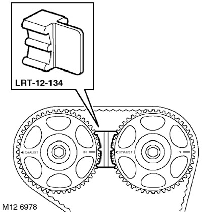
7. Rotate the crankshaft until the marks on the camshaft gears align.
CAUTION: Do not rotate the crankshaft by the camshaft gears, camshaft mounting bolts or timing belt.
8. Install the LRT-12-134 camshaft alignment tool.
9. Remove the pulley from the crankshaft.
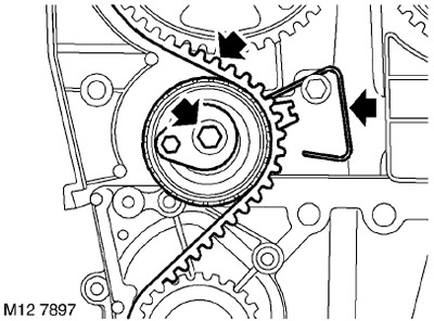
10. Remove and discard the timing belt tensioner mounting bolt.
11. Remove the spring indicator together with the timing belt tensioner.
12. If you intend to continue using the timing belt, mark the direction of its movement.
13. Remove the timing belt.
CAUTION: When removing the timing belt from the camshaft gears, do not use any tools (hands only). Metal objects may damage the belt and gears. Do not rotate the crankshaft with the timing belt removed and the cylinder head installed. The timing belt must be replaced if the cylinder head is to be removed, new gears, a new tensioner or a coolant pump are to be installed. Timing belts must be handled with care. Timing belts should be stored on their edge and with a bending radius not exceeding 50 mm. Do not use a belt that has been twisted or folded in half, as the cord threads may be damaged. Do not use the timing belt if other wear particles (crumbs, threads) are found on the belt cover in addition to dust. Belts that have covered 72,000 km must be replaced. Do not use timing belts whose surface is contaminated with oil or coolant. The cause of pollution must be eliminated.
Installation
1. Wipe the crankshaft pinion gear, camshaft gears, coolant pump wheel and tensioner roller.
ATTENTION: If the gears manufactured by sintering (powder metallurgy technology) have been in contact with oil for a long time, they must be soaked in a solvent and then washed in a clean solvent before installation. The porous structure of the sintered material absorbs oil, which, when released, will contaminate the timing belt.
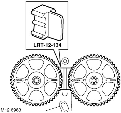
2. Check that the timing marks on the camshaft gears are aligned and that the LRT-12-134 tool holds the gears together.
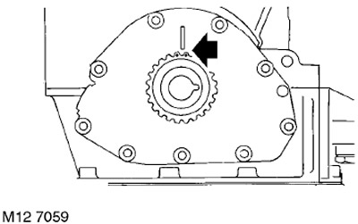
3. Check the position of the marks on the crankshaft drive gear relative to the mark on the oil pump housing (90° before TDC).
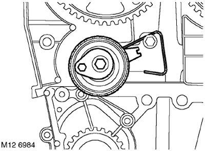
4. Position the spring indicator so that it is above the bolt on the right and so that the tensioner lever is at the 9 o'clock position.
5. Screw in the new special one and tighten it just enough so that the tensioner lever can just barely be moved.
6. Put on the timing belt without using tools (only by hand). During installation of the belt, its branch between the toothed wheels of the intake and exhaust camshafts must remain taut.
CAUTION: If the old timing belt is used, the rotation mark must point in the correct direction.
7. Check that the belt is completely on all gears and rollers.
8. Install the lower front timing belt cover.
ENGINE - MODIFICATION K, volume 1.8, Front exhaust camshaft oil seal, Lower part of the front timing belt cover: vehicles without air conditioning.
9. Temporarily install the pulley on the crankshaft, screw in and lightly tighten the bolt.
10. Remove the LRT-12-134 camshaft alignment tool.
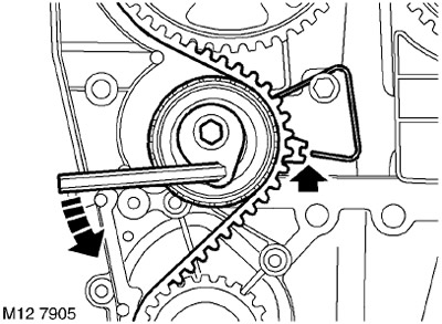
11. Using a 6mm Allen key, turn the tensioner counterclockwise until the notch on the tensioner pointer aligns with the spring indicator.
NOTE: If installing an old belt, the spring indicator must be aligned with the bottom edge of the pointer.
CAUTION: The tensioner pointer must approach the spring indicator from above. If the tensioner pointer passes the spring indicator, the tensioner must be completely pulled back and the operation repeated.
12. After checking the correct position of the pointer relative to the indicator, tighten the tensioner bolt to a torque of 22 Nm.

13. Turn the crankshaft 2 revolutions until the marks on the camshaft gears align.
CAUTION: Do not rotate the crankshaft by the camshaft gears, camshaft mounting bolts or timing belt.
14. Check that the tensioner pointer is positioned correctly relative to the indicator.
15. If the position needs to be corrected, loosen the tensioner mounting bolt enough so that the lever can be moved with greater force. Turn the lever clockwise until the tension on the belt is completely released, then turn the lever clockwise until the pointer is correctly aligned with the indicator.
16. After checking the correct position of the pointer relative to the indicator, tighten the tensioner bolt to a torque of 22 Nm.
17. Turn the crankshaft 2 revolutions until the marks on the camshaft gears align.
18. Check the position of the pointer relative to the indicator; if necessary, repeat the operation described above.
19. Remove the pulley from the crankshaft.
20. Install the LRT-12-145 flywheel stopper onto the engine through the starter opening and secure it with two bolts.
21. Install the upper part of the timing belt cover.
ENGINE - MODIFICATION K, volume 1.8, Front exhaust camshaft oil seal, Upper timing drive cover.
22. Install the hydraulic support.
ENGINE - MODIFICATION K, volume 1.8, Front exhaust camshaft oil seal, Right engine hydraulic support.
23. Connect the negative battery terminal.
Comments on this article