Contents: Control unit ⇩ Injectors ⇩ Idle air control valve ⇩ Oxygen sensor (models with a…⇩ Fuel pressure regulator ⇩ Throttle position sensor ⇩ Trimmer resistor ⇩ Location of injection system…⇩ Fan capacitor ⇩ Location of injection system…⇩ Relay module ⇩
In the fuel system (injection system) MFI uses a hot-wire air flow sensor. The control unit, based on sensor signals, calculates the fuel supply depending on the engine speed and load conditions. Signals for opening and closing the injectors are given in the order of operation of the engine cylinders.
Control unit
The MFI system uses a 14 CUX control unit with a 40-pin connector.
Injectors
Eight injectors are installed in the fuel and intake manifolds. The electromagnetic valve of the injectors is triggered by signals from the control unit.
Idle air control valve
The valve is installed on the resonance chamber. The valve has two windings that open or close the valve based on signals from the control unit, maintaining the idle speed.
Oxygen sensor (models with a neutralizer)
Two sensors are installed in front of the neutralizer on the exhaust system's inlet pipes. The sensor signals are included in the mixture composition control circuit with feedback. For quick start-up, the sensors have electric heating coils.
Fuel pressure regulator
The regulator is mounted on the fuel manifold and has a spring and a vacuum chamber diaphragm to maintain a constant fuel pressure of 2.5 bar.
Throttle position sensor
The sensor is included in the adapted control circuit, so no adjustment of the sensor position is required.
Trimmer resistor
Depending on the engine parameter requirements in different countries, different values of the trimmer resistor are set between terminals 5 and 27. The resistor itself is installed on the control unit housing. Nominal resistance of the resistor:
- red wire - 180 ohms for Australia;green wire - 470 Ohm for Europe, without neutralizer;
- white wire - 389 Ohm for Europe, with neutralizer;
- yellow wire - 910 Ohm, Saudi Arabia, without neutralizer.
Location of injection system components on the engine
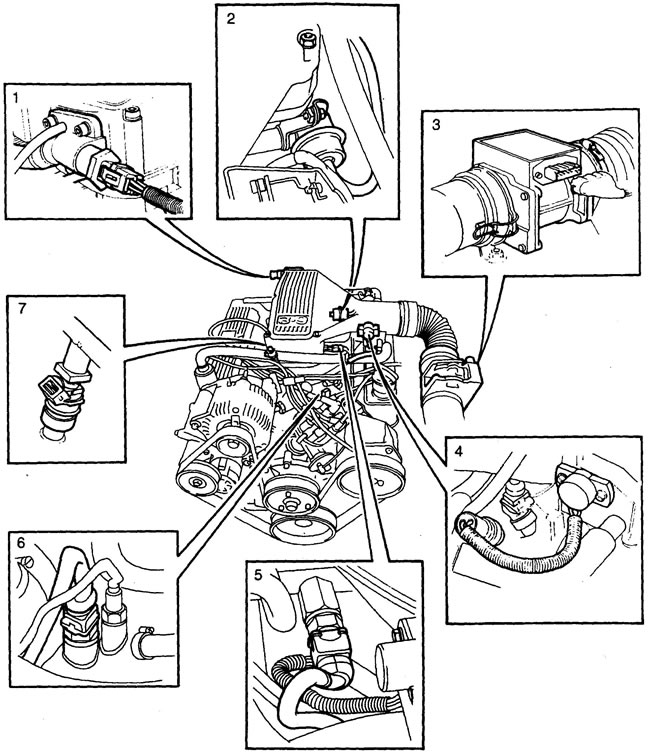
1 - valve (stepper motor) idle speed adjustment, 2 - fuel pressure regulator, 3 - air flow sensor, 4 - throttle position sensor, 5 - fuel temperature sensor, 6 - coolant temperature sensor, 7 - injector.
Fan capacitor
The capacitor is designed to keep the cooling system fan running for some time after the engine is turned off to prevent the liquid from boiling.
Location of injection system components on the frame
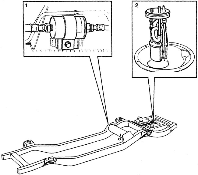
1 - fuel filter, 2 * fuel pump (in tank).
Fuel inertia switch The inertia switch is installed on the engine compartment bulkhead next to the washer reservoir. In the event of an accident, the switch breaks the power supply circuit to the fuel pump. After the switch is triggered, its functionality is restored by pressing the switch button.
Caution: Before pressing the switch button, check the integrity of the power system.
Relay module
Two fuel injection system relays are located on the right side, at the bottom of the A-pillar. The main relay supplies power to the control unit, and the fuel pump relay activates the fuel pump.
Attention:
- 1. The injection system measuring instruments are sensitive to dirt. Work on the fuel injection system and engine management system components must be carried out in absolute cleanliness. Before disconnecting the fuel lines, it is necessary to relieve residual fuel pressure. After disconnecting the fuel lines, plug the connection points.
- 2. On models with a catalytic converter: do not allow the engine to misfire - this will lead to failure of the catalytic converter.
If misfires occur, turn off the engine immediately and correct the problem. Before applying load to the engine after troubleshooting, let the engine run for 3-4 minutes at idle speed at 1500 rpm to purge the neutralizer of fuel.
Comments on this article