2. Relieve residual fuel pressure in the system, disconnect the fuel supply line.
Attention: perform the next step only on a cold engine.
3. Disconnect the lower radiator hose and drain the coolant.
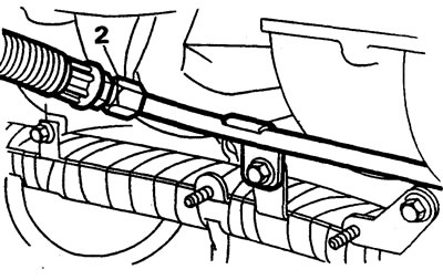
4. Disconnect the hose from the heater pipe.
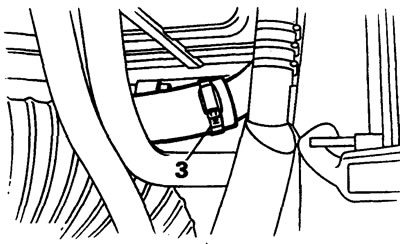
5. Disconnect the connectors of the two coolant temperature sensors.
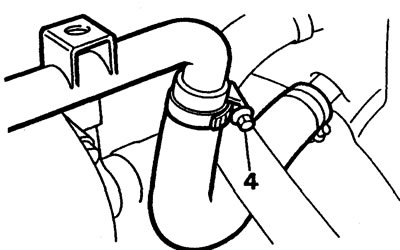
6. Disconnect the upper and bypass hoses of the cooling system.
7. Cut off the plastic cable tie that supports the wiring.
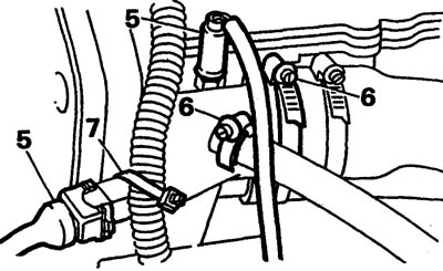
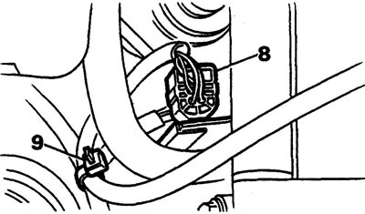
8. Disconnect the oxygen sensor connector.
9. Cut off the plastic cable tie that supports the wiring.
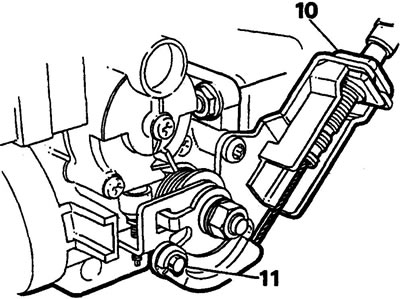
10. Remove the accelerator cable from the bracket.
11. Disconnect the accelerator cable from the throttle cam. Remove the coolant hoses from the throttle body.
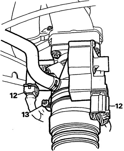
12. Disconnect the stepper motor and throttle position sensor connectors.
13. Disconnect the hose between the air cleaner and the throttle body.
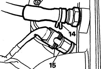
14. Disconnect the brake booster hose from the intake manifold.
15. Disconnect the fuel temperature sensor connector.
16. Remove 3 bolts from the wiring support bracket.
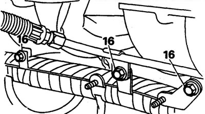
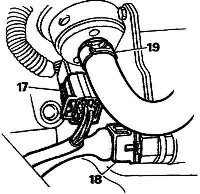
17. Disconnect the injector connector.
18. Disconnect the air temperature sensor connector.
19. Disconnect the fuel line from the fuel pressure regulator.
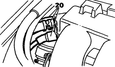
20. Disconnect three hoses from the fuel manifold.
21. Remove the bolt securing the oil dipstick tube to the cooling system pipe.
22. Raise the car.
23. Disconnect the 4 nuts securing the exhaust pipe to the intake manifold.
24. Disconnect the exhaust pipe.
25. Remove the exhaust pipe gasket.
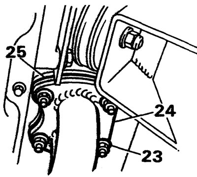
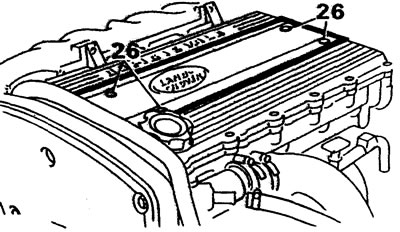
26. Unscrew 4 screws and remove the spark plug cover.
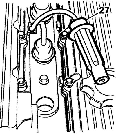
27. Remove the high-voltage wires from the spark plugs and place them aside.
28. Remove the valve covers.
29. Remove the timing belt.
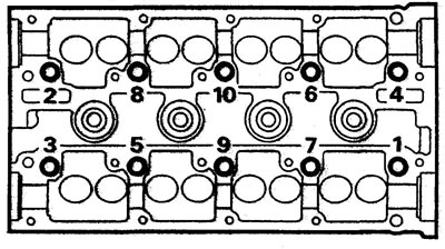
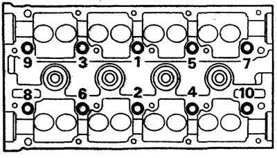
30. In several steps, in the sequence shown in the figure, unscrew the head mounting bolts.
31. Remove the head together with the manifolds.
32. Remove and discard the head gasket.
33. Remove the guide pins from the block.
34. Check the head for cracks, damage and burnouts.
35. Inspect the cylinder block. Make sure that the oil supply jet to the heads is clean and is below the block mating surface.
36. Remove any remaining gasket from the block and head extension surfaces.
37. Check the planes of the block and head by applying a ruler along, across and diagonally to the plane. Maximum deviation from plane is 0.1 mm.
38. Clean the threaded holes with an M11x1.5 tap, dry the threaded holes.
Installation
1. Install the guide pins into the block.
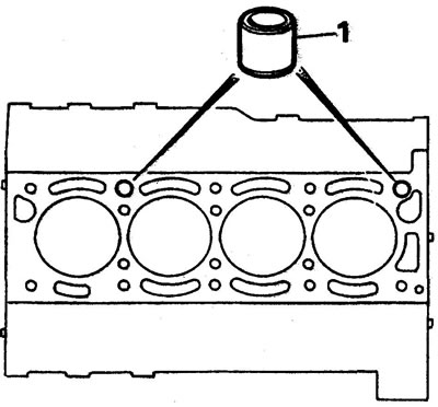
2. Place the head gasket on the block.
3. Place the cylinder head on the block.
4. Lightly lubricate the threads of the head bolts.
5. Tighten the head mounting bolts in several stages in the sequence shown in the figure, see specification.
6. Reinstall the removed parts (in the reverse order of removal).
Comments on this article