Disassembly
Attention: Mark the installation locations of the parts. Differential bearing caps are not interchangeable.
1. Remove the axle shafts and final drive.
2. Remove the bearing ring retainer pin and remove the retainer.
3. Loosen the bearing cap mounting bolts and mark the caps.
4. Using the LRT-54-508 key, unscrew the adjusting rings.
5. Unscrew the bolts and remove the bearing caps.
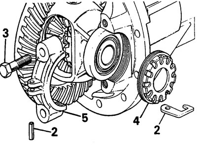
6. Remove the final drive driven gear together with the differential.
For front differential only
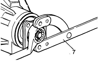
7. Holding the differential flange with the LRT-51-003 wrench, unscrew the flange mounting nut.
8. Remove the washer and pinion flange.
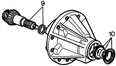
9. Remove the drive gear together with the inner bearing and adjusting rings.
10. Remove the oil seal, spacer and outer bearing.
For rear differential only
7. Using the LRT-51-008 puller, remove the pinion flange centering sleeve.
8. Holding the differential flange with the LRT-51-003 key, unscrew the flange mounting nut.
9. Remove the drive gear together with the inner bearing and adjusting rings.
10. Remove the oil seal, spacer and outer bearing.
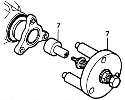
11. Using the LRT-51-505 puller, remove the outer bearing ring and adjusting washers.
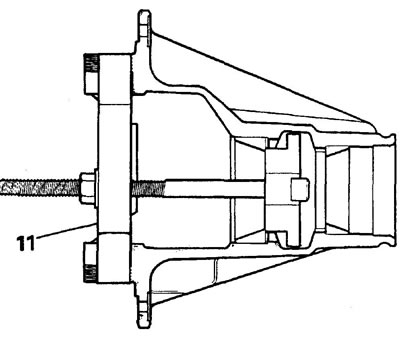
12. Using the LRT-99-002 tool, remove the inner bearing ring from the drive gear shaft.
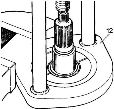
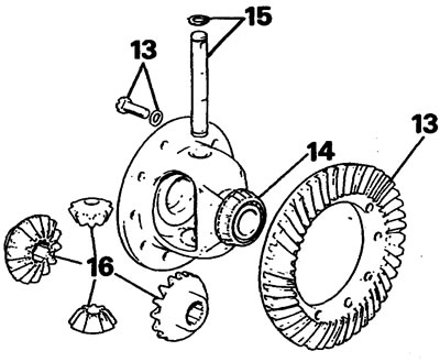
13. Loosen the bolts securing the driven gear of the main transmission to the differential cup and remove the gear.
14. Remove the differential cup bearings.
15. Remove the satellite axle retaining rings and take out the axle.
16. Remove the satellites.
17. Wash the removed parts.
Examination
18. Check the condition of the bearings (wear, pitting).
19. Check the condition of the gears (wear, chipped teeth).
20. Replace defective parts.
Assembly
Satellites
21. Install the satellites into the differential cup.
22. Install the satellite shaft and retaining rings.
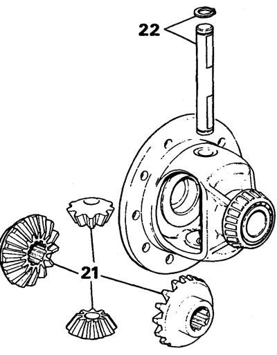
23. Check the freedom of rotation of the satellites and the absence of excessive axial movement. If necessary, replace the satellites or differential cup.
24. Check the alignment of the marks on the driven and driving gears of the main transmission.
25. Install the final drive driven gear.
26. Install the differential cup bearings.
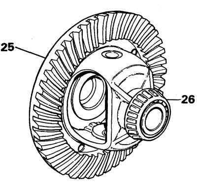
27. Install the differential cup into the final drive housing.
28. Install the bearing caps and hand tighten the cap mounting bolts.
29. Install the adjusting nuts, select the axial clearance of the bearings.
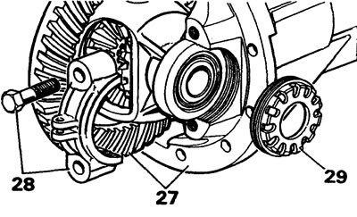
30. Tighten the bearing cap bolts to 90 Nm.
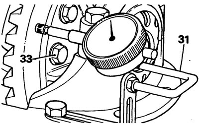
31. Check the runout of the driven gear. If the runout exceeds 0.1 mm, change the position of the gear. If necessary, replace the final drive housing.
32. Remove the differential.
33. Loosen the bolts securing the driven gear of the main transmission, apply Loctite "STUDLOCK" glue to their threads, and tighten the bolts to a torque of 58 N·m.
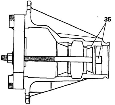
34. Install the outer bearing ring into the drive gear housing and place the adjusting washers. If installing new parts, use shims of minimum thickness (1.27 mm). Install the bearing race using LRT-54-505/506 drifts.
35. Using LRT-54-505/507 mandrels, install the inner bearing ring into the drive gear housing.
36. Using the LRT-54-502 mandrel, install the inner bearing race onto the drive gear shaft.
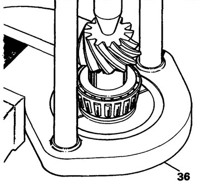
37. Install the drive gear without adjusting washers to determine the bearing preload.
38. Install the outer bearing and spacer (front differential).
39. Install the flange, washer and nut.
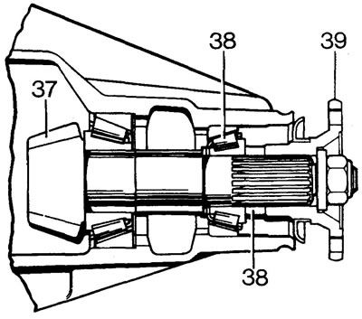
40. There is no need to install the oil seal now.
41. Tighten the flange mounting nut until the pinion shaft rotation torque is 3 Nm (new bearing) or 1.5 N·m (used bearing).
42. On the end of the gear opposite the serial number, the actual size of the gear is marked. Numbers are given in thousandths of an inch. (+) indicates underestimation, (-) indicates overestimation during installation.
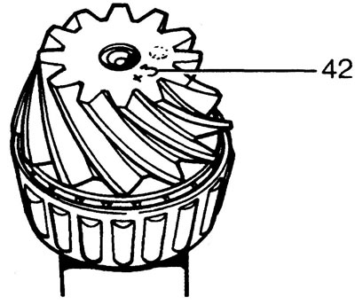
43. The nominal size is determined by the caliber LRT-54-503.
Adjusting the engagement in the final drive
44. Make sure there are no burrs near the marking on the end of the gear.
45. Remove the protective cap from the magnetic base of the indicator stand.
46. Install the indicator and adjustment bar on the marking plate. Set the indicator to zero.
Note: The adjustment bar has three basic sizes. For this differential, set the indicator to size 39.5 mm.
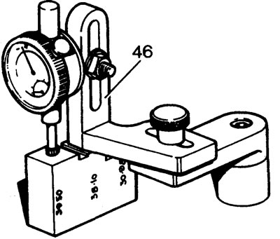
47. Set the indicator to the diameter of the differential bearing bed. Record the indicator reading at the lowest point of the bed.
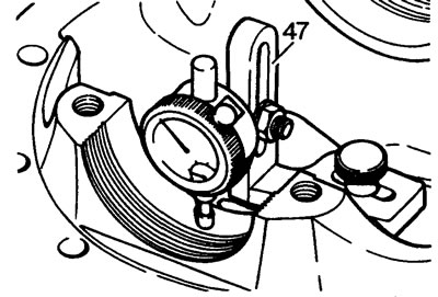
48. Make similar measurements for the second bearing. Calculate the arithmetic mean of two measurements (remember the direction of movement of the indicator leg from zero):
- A. If the indicator leg moves downwards, the thickness of the adjusting washer must be reduced from the size of the one already installed.
- B. If the indicator leg moves upward, the thickness of the adjusting washer must be increased from the size of the one already installed.
Adjustment washers are available in 0.046-0.061-inch thicknesses in 0.001-inch increments.
49. Check the marking on the end of the drive gear. If the marking has a (+) sign, reduce the thickness of the adjusting washer by the specified amount (thousandths of an inch).
50. If the marking has a (-) sign, increase the thickness of the adjusting washer by the specified value (thousandths of an inch). Place the adjusting washer under the gear bearing.
51. Double-check the correct adjustment of the drive gear height: the indicator readings should be equal to the marking applied to the end of the gear. For example: the marking "+3" is applied. The indicator reading should be equal to 0.003" (0.075 mm).
Adjusting bearing preload
52. Remove the flange, pinion gear, outer bearing ring and spacer.
53. Install the previously removed preload adjusting washer onto the gear shaft. If the old washer is lost or unsuitable for installation, install a 2.155 mm thick washer.
54. Install the pinion gear, outer bearing ring and spacer (for front differential only).
55. Install the flange, washer and nut.
56. There is no need to install the oil seal at this stage.
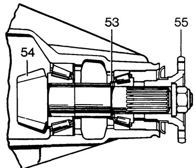
57. Tighten the flange mounting nut to a torque of 130 Nm: the shaft turning torque with new bearings should be 3 Nm, and when installing old bearings - 1.5 Nm.
Replace the adjusting washer if necessary (increasing the thickness of the washer reduces the preload value).
Adjustment washers are available in 0.058-0.085-inch thicknesses in 0.001-inch increments.
58. Remove the flange.
Installing the pinion seal
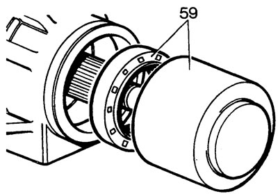
59. Lubricate the oil seal with grease. Install the oil seal using the LRT-51-001 mandrel into the drive gear housing (sealing edge inward).
Installing the pinion flange (front differential)
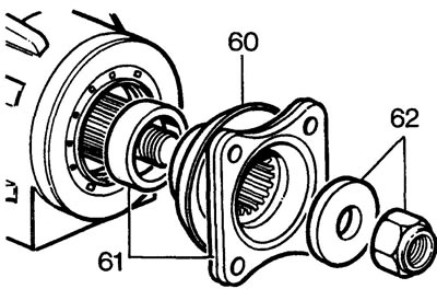
60. Lubricate the sealing lip of the oil seal with transmission oil.
61. Install the spacer and flange on the drive gear shaft.
62. Install the washer and new flange mounting nut. Tighten the nut to a torque of 130 Nm.
Installing the pinion flange (rear differential)
60. Lubricate the sealing lip of the oil seal with transmission oil.
61. Install the flange and new mounting nut onto the drive gear shaft. Tighten the nut to a torque of 130 Nm.
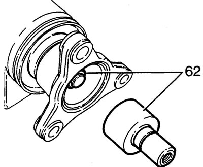
62. Apply Loctite 601 or 638 adhesive to the centering insert and install it into the flange over the mounting nut.
Comments on this article