NOTE: Right brake shown, left brake of similar design.
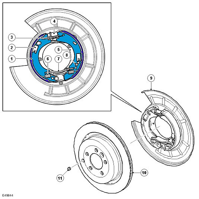
| Item name | Spare part number | Description |
| 1 | Brake shoe | |
| 2 | Locating pin and pad clamp | |
| 3 | Adjusting spring | |
| 4 | Gear adjuster | |
| 5 | support shield | |
| 6 | return spring | |
| 7 | Cross brace | |
| 8 | Wedge adjuster screw | |
| 9 | dust shield | |
| 10 | Rear brake disc | |
| 11 | Regulator access plug |
Each drum brake contains a pair of brake shoes mounted on a support plate that attaches to the rear hub holder. The brake pads are inside a drum built into the rear brake disc. Brake pad orientation LH (left) and RH (right) brake mechanisms differ by 180°.
When the parking brake control unit tightens the cables, this force is transmitted to the drive lever on one of the brake shoes. The drive arm pivots about the cross strut, which spreads the brake pads and brings them into contact with the rear brake disc drum. The gap between the brake shoe and the drum is set using two mechanical adjusters, which are accessed through a hole in the brake disc. One of the regulators has a conventional gear design. The second regulator is a wedge regulator driven by a hex head screw.
After replacing the brake pads or brake discs, a burn-in procedure must be performed to ensure that the drum brakes function properly. For more information refer to Parking Brake Shoe and Lining Adjustment (206-05 Parking Brake and Actuation).
Before removing the brake disc from the vehicle, turn off the power to the parking brake control unit. Operating the parking brake switch with the brake disc released can cause the parking brake control unit actuator to jam.
Comments on this article