car logo Ford
car logo Volkswagen
car logo BMW
car logo Opel
car logo Audi
car logo Toyota
car logo Peugeot
English Русский
Български
Беларускі
Український
Српски
Hrvatski
Română
Polski
Slovenský
Magyar


Main
Freelander
Discovery
Range Rover
Defender
Contacts
Articles

Parking brake control unit (Discovery 3)

 
  • Main
  • Discovery
  • Discovery 3
  • Chassis
  • Parking brake
  • Parking brake control unit
 
        0  
Contents: Internal structure of the parking…⇩ Inputs and outputs ⇩ Parking Brake Control Unit Connector…⇩ Parking Brake Control Unit Connector…⇩
The parking brake control unit monitors external and internal input signals and adjusts the brake cable tension to control the operation of the drum brakes according to the required parking brake operation.

The parking brake control unit is mounted on a support bracket attached to the front of the spare tire carrier. Two rubber mounts mounted on brackets at the bottom of the parking brake control unit fit into holes in the support bracket. The upper corners of the parking brake control unit are secured to the support bracket with rubber mounts and flange nuts.

Main components and parts of the parking brake control unit:
  • Printed circuit board with ASIC (specialized integrated circuit), which provides control of the parking brake.
  • Electric motor.
  • Reducer.
  • Splined shaft.
  • Force sensor.

The spline shaft and the force sensor are connected by a lock at the end of the spline shaft. The spline shaft rotates on the lock and moves axially in the gearbox. The lock and the force sensor move in the channel of the parking brake control unit housing.

To engage and disengage the drum brakes, the parking brake control unit turns on an electric motor, which drives a gearbox. The gearbox turns a splined shaft, increasing or decreasing the tension of the brake cables. The parking brake control unit monitors the load applied to the brake cables using a signal from the force sensor.


Internal structure of the parking brake control unit
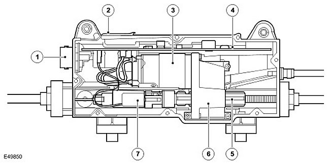

Internal structure of the parking brake control unit


Item nameSpare part catalog numberDescription
1Electrical connector
2Frame
3Electric motor
4PCB
5Splined shaft
6Reducer
7Force sensor

Inputs and outputs


On the RH (right) side of the parking brake control unit there is a 32-pin connector that provides a connection between the printed circuit board and the vehicle's electrical wiring.

Power is supplied to the parking brake control unit via two permanent lines from the BJB (battery Distribution Box). Two other connections with CJB (central electrical distribution box) are designed to transmit voltage signals when the key is inserted into the ignition switch and when the key is in position II (ignition on). Other permanent wiring connections are provided to carry signals from the parking brake switch and, for manual transmission models, the clutch pedal position sensor signal.

In addition to permanent wire connections, the parking brake control unit is connected to a high-speed CAN bus. (controller network) to exchange data with other vehicle systems.

Parking Brake Control Unit Connector C2178
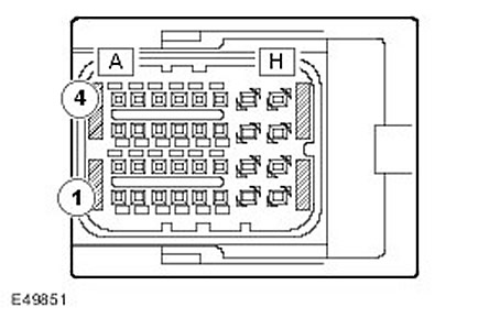

Parking Brake Control Unit Connector C2178


The article was taken from this resource LRman.ru


Parking Brake Control Unit Connector Pins C2178


Contact No.DescriptionLogin/Logout
A1Not used-
A2High Speed CAN Bus Low Level Output (controller network)Login/Logout
A3High Speed CAN Bus High Level Input (controller network)Login/Logout
A4High Speed CAN Bus Low Input (controller network)Login/Logout
B1Not used-
B2High-speed CAN bus high level output (controller network)Login/Logout
B3Parking brake switch SW1Entrance
B4Parking brake switch SW4Entrance
C1 and C2Not used-
C3Parking brake switch SW2Entrance
C4Parking brake switch SW5Exit
D1 - E1Not used-
E2Clutch Pedal Position Sensor GroundEntrance
E3Clutch Pedal Position Sensor SignalEntrance
E4Power supply for the clutch pedal position sensorExit
F1Not used-
F2The key is in the ignitionEntrance
F3Ignition supplyEntrance
F4Red parking brake indicatorExit
G1Not used-
G2WeightExit
G3Not used-
G4Powered by batteryEntrance
H1Not used-
H2WeightExit
H3Not used-
H4Powered by batteryEntrance


This article is available at russian, bulgarian, belarusian, ukrainian, serbian, croatian, romanian, polish, slovak, hungarian
Article review: Saveliy Ushakov


Previous articles
Parking brake specification
Location of units and parts
Parking brake switch
Drum brakes
Parking brake cables
Emergency release rope
Clutch Pedal Position Sensor
Parking brake indicators

Current article
Parking brake control unit

Next articles
How the parking brake works
Handbrake control diagram
Inspection and check of the handbrake
DTC Trouble Code Index
Running-in of parking brake pads
Adjusting the parking brake pads and linings
Parking brake shoes
Left parking brake cable


Similar articles from Land Rover repair manuals:
• Parking brake control Freelander 2 (2006-2014)
• Electronic control unit (ECU) — parking assistance — models from 04MY Freelander 1 (1997-2006)
• Electronic control unit parking assistance system Range Rover 3 (2001-2012)
• Parking brake switch Defender 2007+ (2007-2016)

Comments on this article


No comments yet


How much will 18 + 44 =


Discovery 3 
  • General information
  • Using the manual
  • Precautionary measures
  • Service Information
  • Technique
  • Health protection
  • Road test
  • Identification codes
  • Jacking and lifting
  • Maintenance - diesel
  • Maintenance - petrol
  • Chassis
  • Suspension
  • Front suspension
  • Rear suspension
  • Wheels and tires
  • Dynamic suspension
  • Cardan shaft
  • Rear drive axle
  • Front drive axle
  • Front axle axles
  • Rear axle axles
  • Brake system
  • Parking brake
  • Hydraulic brake
  • Vacuum brake booster
  • Anti-lock braking system
  • Steering
  • Steering column
  • Power unit
  • Petrol engine 4.0L
  • Petrol engine 4.4L
  • Diesel engine 2.7L
  • Engine cooling
  • Fuel supply
  • Drive units
  • Launch system
  • Ignition system
  • Emission reduction
  • Air filtration
  • Fuel vapor control
  • Electronic control part
  • Car gearbox
  • Clutch
  • All-wheel drive systems
  • Transfer case
  • Exhaust system
  • Fuel tank and lines
  • Acceleration control
  • Electrical equipment
  • Climate control
  • Instruments and control lamps
  • Battery and charging system
  • Information system
  • Lighting and headlights
  • Power distribution
  • Electronic Function Group
  • Body and coating
  • Body elements
  • Interior and body trim
  • Mirrors and glasses
  • Seats
  • Instrument panel and console
  • Handles and locks
  • Windshield wipers and washers
  • Sunroof and bumpers
  • Safety system
  • Body repairs
  • Repair of front end elements
  • Repair of back elements
  • Side panel repair
  • Frame and body mount

Discovery 1 
  • General information
  • Technical specifications
  • Introduction to manual
  • Troubleshooting
  • Power unit
  • Diesel engine Tdi
  • Petrol engine V8i (3.9 l)
  • Petrol engine V8i (4.0 l)
  • Petrol engine Mpi
  • Reducing harmful emissions
  • Fuel system Tdi
  • Fuel system MFi
  • Fuel system SFi
  • Fuel system MPi (MEMS)
  • Cruise control
  • Cooling system (Tdi)
  • Cooling system (V8i)
  • Cooling system (MPi)
  • Exhaust system
  • Transmission
  • Clutch
  • Manual gearbox R380
  • Manual gearbox LT 77
  • Transfer case LT230T
  • Automatic gearbox
  • Cardan shaft
  • Rear axle
  • Front axle
  • Chassis
  • Steering system
  • Front suspension
  • Rear suspension
  • Brake system
  • Wheels and tires
  • Body and interior
  • Passive safety
  • Doors, locks and windows
  • Exterior body parts
  • Interior trim details
  • Seats
  • Electrical equipment
  • Heating and ventilation
  • Air conditioning
  • Windscreen wipers
  • Starting and charging system
  • Equipment and devices
  • Lighting and headlights


LRman.ru © 2013-2026 | Mobile version | Free Lander | Discovery | Range Rover | Defender | Contacts | | Sitemap |
Car repair and service instructions Land Rover: Freelander, Discovery, Range Rover, Defender
We use cookies to make pages load faster and provide a more user-friendly experience 🍪