car logo Ford
car logo Volkswagen
car logo BMW
car logo Opel
car logo Audi
car logo Toyota
car logo Peugeot
English Русский
Български
Беларускі
Український
Српски
Hrvatski
Română
Polski
Slovenský
Magyar


Main
Freelander
Discovery
Range Rover
Defender
Contacts
Articles

The device and technical description of the generator 4.4L (Discovery 3)

 
  • Main
  • Discovery
  • Discovery 3
  • Electrical equipment
  • Battery and charging system
  • The device and technical description of the generator 4.4L
 
        0  
The device and technical description of the generator 4.4L


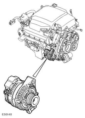
The generator is mounted on the engine cylinder block, on its right side. The generator, manufactured by Denso, has an output current of 85/150 A. A poly V-belt with six grooves is used to drive the generator from the crankshaft pulley.

The main components of the generator are the stator, rotor, rectifier and voltage regulator. The generator body has a three-pin connector C0053:
  • Pin 1 - Reference voltage line to battery via battery junction box (BJB)
  • Pin 2 - Pulse Width Modulation signal from the Engine Control Module (ECM) to the generator (generator control)
  • Pin 3 - Pulse Width Modulation signal from generator to ECM (generator control)
The generator is connected to ground at the mounting points.

The rotor consists of an excitation winding wound on a cast iron core and mounted on a shaft. The rotor core has projections on both sides that form the north and south poles when current flows through the excitation winding. The rotor is located inside the stator, and the rotor shaft is mounted on bearings that ensure smooth rotation and withstand significant lateral loads created by the tension of the drive belt.


The stator has three windings made of copper wire. The three stator windings are connected in a "star" at a common point. The output current is fed into the electrical system from the free ends of the three windings. When the rotor rotates, alternating current is generated in the winding.

The rectifier converts the alternating current generated in the stator windings into direct current. (rectified) the current required to power the vehicle's electrical equipment. The rectifier is a series of semiconductor diodes mounted on a heat sink. The positive and negative sides have the same number of diodes, and an additional diode is installed in the voltage regulator to control the feedback on the battery voltage signal line. The rectifier also prevents the battery from discharging through the alternator when the alternator voltage is lower than the battery voltage.

To protect the battery, an "intelligent" regulator is used to control the generator output voltage. At low temperatures, the battery's ability to recharge is low, so the charging voltage must be increased as much as possible, but at high temperatures, the charging voltage must be reduced to prevent excessive gas formation in the battery and, as a result, loss of water from the electrolyte. The required generator output voltage is calculated by the EMS system, which is responsible for managing the generator. Conventional voltage regulators regulate based on the generator temperature, which means ignoring the battery temperature and long periods of recharging in a non-optimal mode. The new system allows the EMS to set the required voltage based on the battery temperature, the value of which is measured using various sensors, and the generator voltage precisely matches the battery requirements.


The material was taken from the specified website: LRman.ru

Fast acting transistor switches are used to regulate the voltage in the generator. In addition, the regulator transmits a pulse width modulation signal to the ECM, which is used to regulate the idle speed under different electrical loads.

Initially, at low generator speeds, the ignition switch power supply circuit supplies excitation voltage to the rotor winding using brushes and contact rings. As the generator speed increases, a self-excitation effect occurs in it.

The control signal for the battery charge indicator lamp is transmitted to the EMS and then via the CAN bus to the instrument cluster.

Load control system


The load control system includes a program stored in the Automatic Temperature Control (ATC) controller. For more information, refer to Control Components (412-04 Control Components).

The controller is designed to maintain battery charge during abnormal vehicle use. The load control system switches the multimedia equipment and air suspension to economy mode, and also regulates the operation of such consumers as seat heaters and window heaters so that the battery does not discharge to a level at which the vehicle cannot be used. The message center screen will display the message 'WARNING - LOW BATTERY' (warning - low battery).


This article is available at russian, bulgarian, belarusian, ukrainian, serbian, croatian, romanian, polish, slovak, hungarian
Article review: Saveliy Ushakov


Previous articles
Battery specification
Diagnostics and testing of the charging system
Battery and wires
Removal and installation the battery
Shelf for additional battery
Battery installation shelf
Generator and voltage regulator specification
The device and technical description of the generator 4.0L

Current article
The device and technical description of the generator 4.4L

Next articles
The device and technical description of the generator 2.7L
Removal and installation the 4.0L generator
Removal and installation the generator 4.4L
Removal and installation a 2.7L generator


Similar articles from Land Rover repair manuals:
• Technical rubbers Freelander 2 (2006-2014)
• Diagnostic device TESTBOOK Freelander 1 (1997-2006)
• Technical support Range Rover 3 (2001-2012)
• Description and technical data Defender 2007+ (2007-2016)

Comments on this article


No comments yet


How much will 40 + 39 =


Discovery 3 
  • General information
  • Using the manual
  • Precautionary measures
  • Service Information
  • Technique
  • Health protection
  • Road test
  • Identification codes
  • Jacking and lifting
  • Maintenance - diesel
  • Maintenance - petrol
  • Chassis
  • Suspension
  • Front suspension
  • Rear suspension
  • Wheels and tires
  • Dynamic suspension
  • Cardan shaft
  • Rear drive axle
  • Front drive axle
  • Front axle axles
  • Rear axle axles
  • Brake system
  • Parking brake
  • Hydraulic brake
  • Vacuum brake booster
  • Anti-lock braking system
  • Steering
  • Steering column
  • Power unit
  • Petrol engine 4.0L
  • Petrol engine 4.4L
  • Diesel engine 2.7L
  • Engine cooling
  • Fuel supply
  • Drive units
  • Launch system
  • Ignition system
  • Emission reduction
  • Air filtration
  • Fuel vapor control
  • Electronic control part
  • Car gearbox
  • Clutch
  • All-wheel drive systems
  • Transfer case
  • Exhaust system
  • Fuel tank and lines
  • Acceleration control
  • Electrical equipment
  • Climate control
  • Instruments and control lamps
  • Battery and charging system
  • Information system
  • Lighting and headlights
  • Power distribution
  • Electronic Function Group
  • Body and coating
  • Body elements
  • Interior and body trim
  • Mirrors and glasses
  • Seats
  • Instrument panel and console
  • Handles and locks
  • Windshield wipers and washers
  • Sunroof and bumpers
  • Safety system
  • Body repairs
  • Repair of front end elements
  • Repair of back elements
  • Side panel repair
  • Frame and body mount

Discovery 1 
  • General information
  • Technical specifications
  • Introduction to manual
  • Troubleshooting
  • Power unit
  • Diesel engine Tdi
  • Petrol engine V8i (3.9 l)
  • Petrol engine V8i (4.0 l)
  • Petrol engine Mpi
  • Reducing harmful emissions
  • Fuel system Tdi
  • Fuel system MFi
  • Fuel system SFi
  • Fuel system MPi (MEMS)
  • Cruise control
  • Cooling system (Tdi)
  • Cooling system (V8i)
  • Cooling system (MPi)
  • Exhaust system
  • Transmission
  • Clutch
  • Manual gearbox R380
  • Manual gearbox LT 77
  • Transfer case LT230T
  • Automatic gearbox
  • Cardan shaft
  • Rear axle
  • Front axle
  • Chassis
  • Steering system
  • Front suspension
  • Rear suspension
  • Brake system
  • Wheels and tires
  • Body and interior
  • Passive safety
  • Doors, locks and windows
  • Exterior body parts
  • Interior trim details
  • Seats
  • Electrical equipment
  • Heating and ventilation
  • Air conditioning
  • Windscreen wipers
  • Starting and charging system
  • Equipment and devices
  • Lighting and headlights


LRman.ru © 2013-2026 | Mobile version | Free Lander | Discovery | Range Rover | Defender | Contacts | | Sitemap |
Car repair and service instructions Land Rover: Freelander, Discovery, Range Rover, Defender
We use cookies to make pages load faster and provide a more user-friendly experience 🍪