Contents: Camshaft Position Sensor (CMP) ⇩ Crankshaft Position Sensor (CKP) ⇩ Combined Mass Air Flow/Intake Air…⇩ Coolant temperature sensor ⇩ Coolant Temperature Sensor…⇩ Engine oil temperature sensor ⇩ Oil temperature sensor…⇩ Fuel rail temperature sensor ⇩ Brake light switch ⇩ Glow plugs ⇩ Intake Air Temperature Sensor…⇩
Camshaft Position Sensor (CMP)
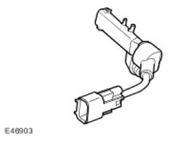
CMP sensor (crankshaft position) is located on the front surface of the left cylinder head. The tip of the sensor passes through the wall and senses the passage of the timing rotor, located behind the camshaft pulley. CMP sensor (crankshaft position) is a Hall sensor.
ECM (engine control unit) uses CMP sensor signal (crankshaft position), to determine whether the piston in cylinder #1 is at TDC for injection or at TDC for exhaust. Based on this, the ECM (engine control unit) actuates the required injector to inject fuel into the cylinder when the piston is at TDC for injection.
CMP sensor (crankshaft position) is a Hall effect sensor and is used by the ECM (engine control unit) when starting the engine. ECM (engine control unit) synchronized with CKP sensor signal (crankshaft position). For this ECM (engine control unit) based on the CMP sensor signal (crankshaft position) identifies cylinder #1 to correctly select injection timing. When the ECM (engine control unit) sets the injection timing, CMP sensor signal (crankshaft position) no longer in use.
On the CMP sensor (crankshaft position) 5V power is supplied from the ECM (engine control unit). Two additional ECM electrical circuits (engine control unit) provide grounding and signal transmission.
If a malfunction occurs, the ECM (engine control unit) an error is registered. There are two types of failures: too high a signal frequency or no signal at all. Error registered by the ECM (engine control unit), may also refer to a general crankshaft signal failure or a dynamic crankshaft signal implausibility. Both possibilities must be checked to determine the cause of the failure.
If a CMP sensor malfunction occurs (crankshaft position) when the engine is running, the engine continues to run, but the ECM (engine control unit) disables boost pressure control. After the engine stops, it is restarted (despite the fact that the starter turns the engine) will not be possible as long as the fault code remains in memory.
Crankshaft Position Sensor (CKP)
CKP sensor (crankshaft position) is located at the rear of the cylinder block on the left side. The tip of the sensor is in the plane of rotation of the magnetic disk mounted on the crankshaft. The timing disk is pressed onto the end face of the crankshaft. To obtain a phase-correct signal, the timing wheel must be correctly aligned with respect to the crankshaft. The sensor output produces a rectangular signal with a frequency proportional to the crankshaft rotation frequency.
ECM (engine control unit) monitors the CKP sensor signal (crankshaft position) and can register excess engine speed. ECM (engine control unit) counteracts engine speed increases beyond the permissible limits, gradually reducing the speed synchronization functions. CKP sensor (crankshaft position) is a Hall sensor. The sensor responds to changes in the magnetic field that occur when a magnetized drive wheel rotates.
The timing gear has two missing teeth, equivalent to 6° of crankshaft rotation. The gap of two missing teeth serves to determine the angular position of the crankshaft.
When a section with two missing teeth passes near the tip of the sensor, a gap in the signal occurs, which the ECM (engine control unit) is used to determine the position of the crankshaft. The air gap between the sensor tip and the ring is important because it ensures that the signals sent to the ECM are correct. (engine control unit). Recommended gap between CKP sensor (crankshaft position) and the target is 0.4-1.5 mm.
ECM (engine control unit) uses CKP sensor signal (crankshaft position) to perform the following functions:
- Synchronization.
- Determining the moment when fuel supply begins.
- Fuel Pump Relay Circuit Enabled (after preliminary pumping).
- Formation of the engine crankshaft speed signal, which is distributed via the CAN bus (local area network of controllers) and is used by other systems.
Combined Mass Air Flow/Intake Air Temperature (MAF/IAT) Sensor
(The article is based on information from the website: lrman.ru)
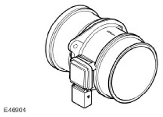
MAF sensor (mass air flow) /IAT (intake air temperature) mounted on the supply air duct directly behind the air filter housing. The sensor housing contains two sensors: the MAF sensor (mass air flow) and IAT sensor (intake air temperature). The sensor is housed in a molded plastic housing that connects the intake manifold and the intake pipe.
MAF sensor operation (mass air flow) is based on the "hot film" principle. The printed circuit contains two film sensing elements. The temperature of one element is maintained at the intake air temperature, for example, 25°C. The second element is heated to 200°C above the intake air temperature, i.e. up to 225°C. The intake air entering the engine passes through the MAF sensor (mass air flow) and has a cooling effect on the film. ECM (engine control unit) monitors the current required to maintain a 200°C difference between the two elements, and uses this difference to generate a precise non-linear signal that corresponds to the volume of air entering the engine.
MAF sensor output signal (mass air flow) is a digital signal proportional to the mass of incoming air. ECM (engine control unit) uses this data, along with signals from other sensors and information from stored fuel maps, to determine the exact amount of fuel that should be injected into the cylinders. The signal is also used as a feedback signal for the EGR system. (exhaust gas recirculation systems).
In the IAT sensor voltage divider circuit (intake air temperature) contains a thermistor with NTC (negative temperature coefficient). NTC thermistor (negative temperature coefficient) works on the principle that the sensor's resistance decreases as the intake air temperature increases. Since the thermistor allows more current to pass to ground, the voltage sensed by the eCm (engine control unit), decreases. The voltage change is proportional to the change in intake air temperature. Using the output voltage from the IAT sensor (intake air temperature), ECM (engine control unit) can adjust the fuel delivery table in relation to the air intake temperature. This correction is important because hot air contains less oxygen than cold air of the same volume.
On the MAF sensor (mass air flow) 12V supply voltage is supplied from BJB (battery mounting box), with the connection to ground being made via the ECM (engine control unit). Two other circuits connected to the ECM (engine control unit), are the signal circuits of the MAF sensors (mass air flow) and IAT (intake air temperature).
IAT sensor (intake air temperature) receives 5V reference voltage from ECM (engine control unit) and shares a common ground circuit with the MAF sensor (mass air flow). IAT sensor output signal (intake air temperature) processed by ECM (engine control unit) by monitoring changes in the reference voltage supplied to the IAT sensor voltage divider circuit (intake air temperature).
ECM (engine control unit) checks the calculated air mass by comparing it with the engine speed. If the calculated air mass value is not plausible, the ECM (engine control unit) uses a default mass air flow value that is generated based on the average engine speed compared to stored characteristic tables. The mass air flow value is then adjusted to take into account boost pressure, atmospheric pressure and air temperature.
If the MAF sensor (mass air flow) eCM fails (engine control unit) implements a default strategy based on engine speed. In case of MAF sensor signal failure (mass air flow) any of the following signs of malfunction may be observed:
- Difficult start
- Engine stalls after starting
- The engine responds sluggishly to the accelerator pedal
- Malfunction of the emission control system
- Engine crankshaft speed control malfunction in idle mode
- Deterioration of engine energy performance
If the IAT sensor (intake air temperature) eCM fails (engine control unit) uses the default air intake temperature of -5°C. In case of IAT sensor failure (intake air temperature) any of the following signs of malfunction may be observed:
- Increased fuel delivery resulting in black smoke coming out of the exhaust pipe
- Engine crankshaft speed control malfunction in idle mode
Coolant temperature sensor
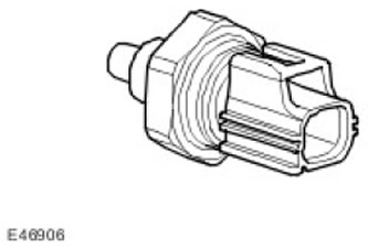
The engine coolant temperature sensor is located in the upper hose at the outlet of the cooling system manifold. ECT sensor (coolant temperature) transmits to the ECM unit (engine control unit) and the instrument panel provides information about the engine coolant temperature.
ECM (engine control unit) uses temperature information to implement the following functions:
- Calculation of fuel cycle supply
- Engine power limitation at excessively high coolant temperature
- Adjusting the operation of the cooling system fan
- Adjusting the operating time of glow plugs
The instrument cluster uses temperature information to operate the temperature gauge. The engine coolant temperature signal is also transmitted by the instrument cluster via the CAN bus. (local area network of controllers) to other systems.
Into the ECM sensor circuit (engine control unit) ECT (coolant temperature) includes an internal voltage divider circuit which includes an NTC thermistor (negative temperature coefficient). As the coolant temperature increases, the sensor resistance drops and vice versa. The output signal of the sensor is a change in voltage, which occurs due to an increase in the current passing to the "ground" with a change in temperature.
ECM (engine control unit) compares the signal voltage with the stored values and adjusts the fuel supply, continuously optimizing controllability. Due to fuel condensation on the cold walls of the combustion chamber, the engine requires increased cyclic supply at low coolant temperatures. To enrich the fuel-air mixture, the ECM (engine control unit) increases the duration of the injector opening. As the engine warms up, the mixture becomes leaner.
The sensor input is a 5V reference voltage supplied from the voltage divider circuit in the ECM. (engine control unit). The sensor ground circuit is also connected to the ECM. (engine control unit), which measures the return current and calculates the sensor resistance value, which corresponds to the coolant temperature.
The following table summarizes the coolant temperature values, corresponding resistance and voltage values.
Coolant Temperature Sensor Characteristics
| Temperature, degrees Celsius | Resistance, kOhm | Voltage, V |
| -40 | 925 | 4,54 |
| -30 | 496 | 4,46 |
| -20 | 277 | 4,34 |
| -10 | 160 | 4,15 |
| 0 | 96 | 3,88 |
| 10 | 59 | 3,52 |
| 20 | 37 | 3,09 |
| 30 | 24 | 2,62 |
| 40 | 16 | 2,15 |
| 50 | 11 | 1,72 |
| 60 | 7,5 | 1,34 |
| 70 | 5,6 | 1,04 |
| 80 | 3,8 | 0,79 |
| 90 | 2,9 | 0,64 |
| 100 | 2,08 | 0,49 |
| 110 | 1,56 | 0,38 |
| 120 | 1,19 | 0,29 |
| 130 | 0,918 | 0,22 |
| 140 | 0,673 | 0,17 |
| 150 | 0,563 | 0,14 |
If the ECT sensor (coolant temperature) is faulty, the following signs of malfunction may be observed:
- Difficulty starting from cold.
- Difficulty starting a hot engine.
- Deterioration of engine performance.
- The temperature indicator does not work or works with a large error
In case of ECT sensor signal failure (coolant temperature) eCM block (engine control unit) uses a default coolant temperature value of 80°C when delivering fuel. In addition, the ECM (engine control unit) continuously runs the cooling fan every time the ignition is turned on, protecting the engine from overheating.
Engine oil temperature sensor
The oil temperature sensor is located in the oil pan. The temperature sensor is an NTC type sensor. (negative temperature coefficient). It operates in a temperature range from -30 degrees Celsius to +150 degrees Celsius.
Oil temperature sensor characteristics
| Temperature, degrees Celsius | Resistance, Ohm |
| 60 | 620 |
| 90 | 255 |
| 120 | 117 |
| 150 | 60 |
Fuel rail temperature sensor
The fuel temperature sensor is located in the return flow line of the left cylinder bank.
The sensor is an NTC type sensor. (negative temperature coefficient) and connected to the ECM (engine control unit) two wires. In the ECM fuel temperature sensor circuit (engine control unit) includes an internal voltage divider circuit which includes an NTC thermistor (negative temperature coefficient). As the temperature increases, the resistance of the sensor decreases. The output signal of the sensor is a change in voltage, which occurs due to the increase in current flowing to the "ground" with a change in temperature.
ECM (engine control unit) constantly monitors the fuel temperature. If the fuel temperature exceeds 85°C, the ECM (engine control unit) activates the engine's "throttling" strategy. The amount of fuel supplied to the injectors is reduced, allowing the fuel to cool. When switching to this mode, the driver may notice a reduction in power.
Further cooling of the fuel is provided in the heat exchanger, where the fuel, upon reaching a certain temperature, is directed by a bimetallic valve. In cars intended for delivery to countries with a hot climate, an electric cooling fan is introduced into the air intake channel of the fuel cooler. The fan is switched on by a bimetallic switch when the fuel reaches a predetermined temperature.
The wires going to the fuel sensor are checked by the ECM (engine control unit) for short circuits and open circuits. ECM (engine control unit) also monitors the 5V supply voltage. If a fault occurs, information about it is recorded in the ECM memory (engine control unit), and ECM (engine control unit) uses the default fuel pressure value.
If ECM (engine control unit) finds that the discrepancy between the pressure sensor signal and the value stored in memory exceeds a preset value, then the ECM memory (engine control unit) a fault code is recorded. Depending on the magnitude of the ECM mismatch (engine control unit) either limit the cyclic feed, or stop the engine immediately, or not allow the next start.
Brake light switch
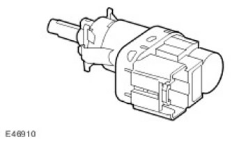
The brake light switch is located on the brake pedal housing and is activated by the brake pedal. The switch is a normally open type and closes when the brake pedal is depressed. The switch is wired directly to the ECM (engine control unit), while in ECM (engine control unit) via CAN bus (local area network of controllers) also comes the brake light signal from the ABS unit (anti-lock braking system).
ECM (engine control unit) uses the brake engagement signal for the following purposes:
- To limit fuel supply during braking
- To disable/cancel speed control when brakes are applied
Switch failure may be accompanied by the following symptoms:
- The speed control system does not work
- Fuel consumption has increased
Glow plugs
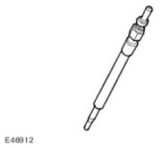
Glow plugs are located in the cylinder heads, on the intake side of each cylinder. Glow plugs and the relay that controls them are essential for ensuring the required starting qualities of the engine. When starting a cold engine, the glow plugs heat the air in the combustion chamber, facilitating the ignition of the fuel. The use of glow plugs allows you to reduce the starting fuel supply and, accordingly, reduce the amount of black smoke. In addition, the use of glow plugs allows you to reduce the starting angle of the injection advance, which reduces the harshness of the engine, especially a cold one, operating in idle mode.
The operation of glow plugs is divided into three phases:
- Preheating
- Operation when cranking the crankshaft
- Post-glow
Preheat is the period of time the spark plugs operate before the starter engages. ECM (engine control unit) regulates the preheating duration based on the output signal of the ECT sensor (coolant temperature) and battery voltage. If the ECT sensor (coolant temperature) faulty, ECM (engine control unit) by default uses the IAT sensor signal (intake air temperature). The preheating time increases at low coolant temperatures and a partially discharged battery.
Postglow is the period of time the spark plugs operate after the engine has started. ECM (engine control unit) regulates the post-glow duration based on the output signal of the ECT sensor (coolant temperature). Post-glow reduces engine noise ("softens" the working process), improves the uniformity of the idle mode and reduces hydrocarbon emissions.
When the ignition key is turned to position II, the glow plug indicator lamp on the instrument panel lights up and the message appears on the information center panel. "PREHEATING" ("PRE-HEATING"). The glow plug indicator lamp operates independently of the glow plugs, so it does not come on during and after starting the engine. When the glow plug indicator lamp is off in the two phases specified, the glow plugs themselves can continue to operate.
If the glow plugs fail, the engine will have difficulty starting and there will be increased smoke after starting the engine.
The glow plug indicator lamp is also used in the EDC system. If a serious fault occurs in the EDC system, the glow plug indicator lamp will illuminate continuously and a message will appear in the instrument cluster. The driver should contact a Land Rover dealer as soon as possible to have the engine management system checked.
Intake Air Temperature Sensor (charge air temperature)
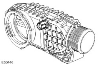
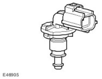
IAT sensor (intake air temperature) located at the rear of the intake plenum just before the electronic throttle valve, the sensor is used to measure the air temperature behind the turbine to adjust the fuel cycle.
Comments on this article