Generator
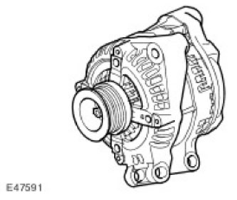
The generator has a multifunctional charging voltage regulator (14 V) and a zener diode rectifier.
ECM (the engine control unit) controls the load of the electrical system by PWM (pulse width modulation) -signals and and regulates the output power of the generator in accordance with the specified load. In addition, ECM (the engine control unit) monitors the battery temperature to determine the generator regulator setpoint. This parameter is needed to protect the battery from damage. At low battery temperatures, its charging capacity is extremely low, and to compensate for this circumstance, it is necessary to increase the charging voltage as much as possible, however, at high temperatures, the charging voltage must be reduced to prevent excessive gas formation and, as a result, loss of water from the electrolyte. For more information refer to Generator (414-02C Generator and Regulator - 2.7L Diesel)
The generator circuit contains intelligent controls that reduce the load on the generator if there is a need to maximize the use of engine torque for other purposes. For such control, three signals are used that come to the ECM (the engine control unit):
- Alternator sensor A measures voltage at CJB (central junction box).
- Generator communication system (Alt Com) transmits the generator voltage setting from the ECM (the engine control unit) into the generator.
- Generator status sensor (Alt Mon) sends to ECM (the engine control unit) current value in the generator load circuit. Through the same signal in the ECM (the engine control unit) fault data is sent, as a result of which the CAN bus (local area network of controllers) a request is sent to the instrument panel to turn on the charging indicator lamp.
Central junction box
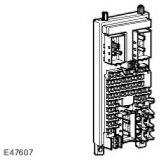
CJB (central junction box) starts the power on and power off routines in the ECM (the engine control unit). When the ignition switch is turned to the ON position, 12 volts is applied to the ignition switch status sensor. The ECM then (the engine control unit) starts the power-up routines and turns on the ECM power relay (the engine control unit); power is supplied to the ECM (the engine control unit) and devices of related systems. After turning off the ignition (OFF position) ECM (the engine control unit) maintains power for 20 seconds through a shutdown procedure and then turns off the ECM power relay (the engine control unit).
Terrain Response System
Road adaptation system (Terrain Response) allows the driver to select a program that adjusts traction and dynamic performance according to the prevailing road conditions.
Various maps are part of the road adaptation system (algorithms) throttle movements corresponding to the different modes of the Terrain Response system. The extreme cases of these algorithms are the sand motion algorithm (rapid increase in torque when pressing the pedal) and movement on grass / gravel / snow (smooth increase in torque).
For the supercharged V8 engine management system, the throttle characteristic change is chosen using a fixed length of time to change from one data card to another. With one position of the pedal, the transition from one card (algorithm) to another occurs in a fixed period of time This means that the transition from card to card (different state of grip) will take the same amount of time. At the same time, the change in torque (torque difference for one pedal position in different algorithms) may be small or significant. In the first case, a reduced vehicle dynamics is selected, in the second, a more dynamic mode. The resulting vehicle acceleration will depend on the difference in torque between the two algorithms and on the selected gears and ranges. The worst-case transition is adjusted so that when using gasoline of different qualities, the user does not lose the feel of the car. For more information refer to Ride and Handling Optimization (204-06 Ride and Handling Optimization)
Comments on this article