Contents: UHEGO/HEGO and MAF/IAT sensors…⇩ CKP sensor (crankshaft position) ⇩ Missed Flash Detection ⇩ Diagnostics using the T4 device ⇩ Road Condition Adaptation System…⇩ Central mounting box ⇩
ECM (engine control unit) has a function for correcting parameters that affect the nature of the control signal. This function enables the engine management system (EMS) to maintain exhaust gas toxicity within the established standards and optimize engine operation in the field of multi-parameter characteristics.
The components for which parameter correction can be performed are the following devices:
- APP sensor (accelerator pedal position sensor)
- Oxygen sensor (HO2S)
- MAF/IAT sensor (intake air temperature)
- CKP sensor (crankshaft position)
- Electronic throttle body
UHEGO/HEGO and MAF/IAT sensors (intake air temperature)
The original article is located on the website www.lrman.ru
The fuel management strategy uses several adaptive data maps. ECM-defined fuel management strategy (engine control unit) includes short-term correction and long-term collection. ECM (engine control unit) monitors the degradation of oxygen sensors over a period of time (HEGO and UHEGO). In addition, the ECM monitors the current correction in the circuit of these sensors.
In cases where the correction parameters go beyond the permissible values of the ECM (engine control unit) records a fault code. At the same time, the ECM (engine control unit) records the crankshaft speed, engine load and intake air temperature.
CKP sensor (crankshaft position)
CKP Sensor Signal Characteristics (crankshaft position) are stored by the ECM unit (engine control unit). This allows the ECM (engine control unit) calculate correction parameters and support the cylinder misfire detection function. Since all flywheels and CKP sensors (crankshaft position) are slightly different from each other, then when replacing (or when removing and installing) any of the named components, the correction parameters must be updated. The correction parameters must also be updated when the ECM is replaced. (engine control unit). ECM (engine control unit) supports four types of CKP sensor signal correction (crankshaft position) by determining the position of the crankshaft (flywheel). Each type of correction refers to a certain range of crankshaft rotation speed. The ranges of crankshaft rotation speeds are characterized in the table:
| Correction | Crankshaft rotation frequency (speed), rpm |
| 1 | 1800 - 3000 |
| 2 | 3001 - 3800 |
| 3 | 3801 - 4600 |
| 4 | 4601 - 5400 |
Missed Flash Detection
Legislation requires that ECM (engine control unit) could detect misfires in the cylinders. The ECM must distinguish between two types (levels) of misfires. The first type of misfire is one that results in a 1.5-fold increase in the total increase in toxic emissions when determined according to the Federal FTP method. The second type of misfire can damage the catalytic converter.
ECM (engine control unit) monitors the number of misfire occurrences in two specified speed ranges. If the number of detected ECMs (engine control unit) if the number of flashes missed in any of the speed ranges exceeds a preset value over two consecutive trips, the ECM (engine control unit) will record the fault code and related parameters: crankshaft speed, engine load and coolant temperature. In addition, the ECM (engine control unit) monitors the number of misfires per 200 crankshaft revolutions. These misfires are assessed for their potential to cause damage to the catalytic converters. If the number of misfires exceeds a certain value, the ECM (engine control unit) will record the neutralizer threat status code and related parameters: crankshaft speed, engine load and coolant temperature.
The shape of the crankshaft position sensor signal depends on the speed of the flywheel relative to the sensor tip. Each time a tooth of the timing gear passes the sensor tip, a sinusoidal signal is formed in the latter. ECM (engine control unit) determines the change in flywheel rotation speed (crankshaft) by changing the shape of the sinusoidal signal coming from the sensor.
Analysis of the received signal allows ECM (engine control unit) detect the fact of a missed flash. At this point in time, the ECM (engine control unit) evaluates the degree of change in the crankshaft position sensor signal and assigns a ripple factor to it. The ripple factor value can be monitored in real time using the T4. ECM (engine control unit) analyzes the signal by several parameters and makes a decision on whether to count the event or not. ECM (engine control unit) can establish the fact of misfiring and assign a coefficient of unevenness in relation to each individual cylinder.
Diagnostics using the T4 device
ECM (engine control unit) stores fault data as DTCs (diagnostic trouble codes) referred to as 'P' codes. 'P' codes are defined by OBD regulations and, along with their associated environmental conditions and freeze frame data, can be read using a third-party diagnostic tool or the T4. The T4 is also capable of reading sensor data, currently used parameter settings, and current fuel, ignition and idle parameters in real time.
| Code number P | Component/signal | Description of the malfunction |
| P0011 | CMP (crankshaft position) /CKP (crankshaft position) /VVT | Position Error, VVT Retard Position Signal High for CMP (crankshaft position) /CKP (crankshaft position) row A |
| P0012 | CMP (crankshaft position) /CKP (crankshaft position) /VVT | Position Error, VVT Retard Position Signal Low for CMP (crankshaft position) /CKP (crankshaft position) row A |
| P0021 | CMP (crankshaft position) /CKP (crankshaft position) /VVT | Position Error, VVT Retard Position Signal High for CMP (crankshaft position) /CKP (crankshaft position) row B |
| P0022 | CMP (crankshaft position) /CKP (crankshaft position) /VVT | Position Error, VVT Retard Position Signal Low for CMP (crankshaft position) /CKP (crankshaft position) row B |
| P0026 | VVT | Low/High Bank A Circuit Malfunction Signal |
| P0028 | VVT | Low/High Bank B Circuit Malfunction Signal |
| P0031 | UHEGO | Low Signal Level in the Control Circuit of the Heater Row A |
| P0032 | UHEGO | Row A Heater Control Circuit High |
| P0051 | UHEGO | Low Signal Level in the Control Circuit of the B-Bank Heater |
| P0052 | UHEGO | Row B Heater Control Circuit High |
| P0069 | HAC | Sensor characteristic/circuit |
| P0071 | Outside air temperature sensor | Characteristic |
| P0072 | Outside air temperature sensor | Low signal level at the input of the circuit |
| P0073 | Outside air temperature sensor | High signal level at the input of the circuit |
| P0075 | VVT | Open circuit in row A |
| P0076 | VVT | Short circuit to ground in the A-row circuit |
| P0077 | VVT | Short circuit to battery in row A circuit |
| P0081 | VVT | Open circuit in row B |
| P0082 | VVT | Short circuit to ground in the B-row circuit |
| P0083 | VVT | Short circuit to battery in row B circuit |
| P0087 | Fuel system | Minor malfunction |
| P0088 | Fuel system | Major malfunction |
| P0089 | Fuel system | Interference |
| P0093 | Fuel system | Major leak |
| P0096 | IAT (intake air temperature) | Sensor characteristics |
| P0101 | AFM | Chain characteristics |
| P102 | AFM | Low signal level at the input of the circuit |
| P103 | AFM | High signal level at the input of the circuit |
| P0106 | MAP ((manifold absolute pressure)) | Sensor characteristics |
| P0107 | MAP ((manifold absolute pressure)) | Low signal level at the input of the circuit |
| P0108 | MAP ((manifold absolute pressure)) | High signal level at the input of the circuit |
| P0111 | IAT (intake air temperature) | Constantly high/low signal level when starting the engine, high level |
| P0112 | IAT (intake air temperature) | Low signal level at the input of the sensor circuit 1 |
| P0113 | IAT (intake air temperature) | High signal level at the input of the sensor circuit 1 |
| P0116 | ECT (coolant temperature) | Invalid signal |
| P0117 | ECT (coolant temperature) | Low signal level at the input of the circuit |
| P0118 | ECT (coolant temperature) | High signal level at the input of the circuit |
| P0121 | Throttle body circuits 1 and 2 | Range/Characteristic |
| P0122 | Throttle Valve Circuit 1 | Low input signal level |
| P0123 | Throttle Valve Circuit 1 | High input signal level |
| P0125 | ECT (coolant temperature) | Insufficient coolant temperature for closed loop control system |
| P0128 | Thermostat control circuit | Low coolant temperature - thermostat stuck open |
| P0131 | UHEGO | Short circuit to ground in the A-row circuit |
| P0132 | UHEGO | Short circuit to battery in row A circuit |
| P0133 | UHEGO | Slow reaction for series A |
| P0136 | HEGO | Setting parameters for row A |
| P0137 | HEGO | Short circuit to ground in the A-row circuit |
| P0138 | HEGO | Short circuit to battery in row A circuit |
| P0139 | HEGO | Slow reaction for series A |
| P0140 | HEGO | No signals for row A |
| P0141 | HEGO | Malfunction in the control circuit of the heater row A |
| P0151 | UHEGO | Short circuit to ground in the B-row circuit |
| P0152 | UHEGO | Short circuit to battery in row B circuit |
| P0153 | UHEGO | Slow reaction for row B |
| P0156 | HEGO | Setting parameters for row B |
| P0157 | HEGO | Short circuit to ground in the B-row circuit |
| P0158 | HEGO | Short circuit to battery in row B circuit |
| P0159 | HEGO | Slow reaction for row B |
| P0160 | HEGO | No signals for row B |
| P0161 | HEGO | Malfunction in the control circuit of the heater of the bank B |
| P00171 | Electronic fuel mixture control | Excessive lean in row A |
| P0172 | Electronic fuel mixture control | Over-enrichment in series A |
| P0174 | Electronic fuel mixture control | Excessive lean in row B |
| P0175 | Electronic fuel mixture control | Over-enrichment in series B |
| P0181 | Fuel Rail Temperature Sensor | Invalid temperature signal |
| P0182 | Fuel Rail Temperature Sensor | Low signal level at the input of the circuit |
| P0183 | Fuel Rail Temperature Sensor | High signal level at the input of the circuit |
| P0191 | Fuel Rail Pressure Sensor | Range/Characteristic |
| P0192 | Fuel Rail Pressure Sensor | Low input signal level |
| P0193 | Fuel Rail Pressure Sensor | High input signal level |
| P0196 | Oil temperature sensor | Range/Characteristic |
| P0197 | Oil temperature sensor | Low input signal level |
| P0198 | Oil temperature sensor | High input signal level |
| P0201 | Injector chain | Cylinder 1 fault |
| P0202 | Injector chain | Cylinder 2 fault |
| P0203 | Injector chain | Cylinder 3 fault |
| P0204 | Injector chain | Cylinder 4 fault |
| P0205 | Injector chain | Cylinder 5 fault |
| P0206 | Injector chain | Cylinder 6 fault |
| P0207 | Injector chain | Cylinder 7 fault |
| P0208 | Injector chain | Cylinder 8 fault |
| P0222 | APP sensor (accelerator pedal position sensor) 2 | Low input signal level |
| P0223 | APP sensor (accelerator pedal position sensor) 2 | High input signal level |
| P0227 | APP sensor (accelerator pedal position sensor) 1 | Low input signal level |
| P0228 | APP sensor (accelerator pedal position sensor) 1 | High input signal level |
| P0229 | APP sensor (accelerator pedal position sensor) | Intermittent malfunction |
| P0297 | Active Speed Control | Exceeding the normal speed of the vehicle |
| P0300 | Misfire | Random misfire/misfire series |
| P0301 | Misfire | Cylinder 1 |
| P0302 | Misfire | Cylinder 2 |
| P0303 | Misfire | Cylinder 3 |
| P0304 | Misfire | Cylinder 4 |
| P0305 | Misfire | Cylinder 5 |
| P0306 | Misfire | Cylinder 6 |
| P0307 | Misfire | Cylinder 7 |
| P0308 | Misfire | Cylinder 8 |
| P0313 | Misfire | Misfire with low fuel level |
| P0316 | Misfire | Misfire detected in first 1000 rpm |
| P0326 | Knock sensor | Incorrect sensor characteristic 1 |
| P0327 | Knock sensor | Low signal level at the input of the sensor of the row A |
| P0328 | Knock sensor | High level signal at the input of the sensor of row A |
| P0331 | Knock sensor | Incorrect sensor characteristic 2 |
| P0332 | Knock sensor | Low signal level at the input of the sensor of the row B |
| P0333 | Knock sensor | High level signal at the input of the sensor of row A |
| P0335 | CKP sensor (crankshaft position) | Sensor circuit fault at start-up/during operation |
| P0336 | CKP sensor (crankshaft position) | Range/Characteristic |
| P0340 | CMP sensor (crankshaft position) at the inlet of row A | Crash on startup/during operation |
| P0341 | CMP sensor (crankshaft position) at the inlet of row A | Range/Characteristic |
| P0345 | CMP sensor (crankshaft position) at the inlet of row B | Crash on startup/during operation |
| P0346 | CMP sensor (crankshaft position) at the inlet of row B | Range/Characteristic |
| P0351 | Ignition coil | Malfunction in cylinder 1 circuit |
| P0352 | Ignition coil | Malfunction in the cylinder 2 circuit |
| P0353 | Ignition coil | Malfunction in the cylinder 3 circuit |
| P0354 | Ignition coil | Malfunction in the cylinder 4 circuit |
| P0355 | Ignition coil | Malfunction in the cylinder 5 circuit |
| P0356 | Ignition coil | Malfunction in the cylinder 6 circuit |
| P0357 | Ignition coil | Malfunction in the cylinder 7 circuit |
| P0358 | Ignition coil | Malfunction in the cylinder 8 circuit |
| P0365 | CMP sensor (crankshaft position) on the release of row A | Crash on startup/during operation |
| P0366 | CMP sensor (crankshaft position) on the release of row A | Range/Characteristic |
| P0390 | CMP sensor (crankshaft position) on the release of row B | Crash on startup/during operation |
| P0391 | CMP sensor (crankshaft position) on the release of row B | Range/Characteristic |
| P0401 | EGR system (exhaust gas recirculation) | Registration of insufficient consumption |
| P0403 | EGR system (exhaust gas recirculation) | Low/High Input Signal Level of Valve Circuit |
| P0405 | Differential pressure sensor | Short circuit to ground |
| P0406 | Differential pressure sensor | Short circuit to battery |
| P0409 | Differential pressure sensor | Characteristic |
| P0420 | Catalytic converter row A | Efficiency below threshold |
| P0430 | Catalytic converter | Efficiency below threshold |
| P0441 | Purge valve | Characteristic |
| P0442 | DMTL | Moderate leak detection |
| P0447 | DMTL | Short circuit to ground |
| P0448 | DMTL | Short circuit to battery |
| P0455 | DMTL | Detecting a major leak |
| P0456 | DMTL | Detecting a small leak |
| P0458 | Purge valve | Short circuit to ground |
| P0459 | Purge valve | Short circuit to battery |
| P0461 | Fuel level sensor | Range/Characteristic |
| P0480 | Radiator Fan Block | Control circuit fault |
| P0493 | Viscous coupling fan | Speed out of range |
| P0501 | Car speed | Range/performance related fault |
| P0504 | Brake switch | Circuit fault |
| P0506 | Idle Speed Control System | RPM is lower than expected |
| P0507 | Idle Speed Control System | RPM is lower than expected |
| P0512 | Crankshaft rotation request circuit | High/low input signal level |
| P0513 | Security system key | Invalid key |
| P0532 | Air conditioning refrigerant pressure sensor | Low input signal level |
| P0533 | Air conditioning refrigerant pressure sensor | High input signal level |
| P0560 | Backup battery | Malfunction |
| P0562 | Sensor power supply | Low input signal level |
| P0563 | Sensor power supply | High input signal level |
| P0566 | Speed Control Override Switch | Malfunction in the on position |
| P0567 | Speed control resume switch | Malfunction in the on position |
| P0568 | Cruise control | Low/high input signal level |
| P0569 | Speed reset/memory/setup switch | Malfunction in the on position |
| P0570 | Speed dial/memory/setup switch | Malfunction in the on position |
| P0574 | Cruise control | Speed control |
| P0576 | Cruise control | Low input signal level |
| P0577 | Cruise control | High input signal level |
| P0604 | ECM self-diagnosis (engine control unit) | RAM error |
| P0605 | ECM self-diagnosis (engine control unit) | ROM error |
| P0606 | ECM self-diagnosis (engine control unit) | CPU error |
| P0616 | Starter relay | Low input signal level |
| P0617 | Starter relay | High input signal level |
| P0627 | Main fuel pump | Lack of commands |
| P0628 | Fuel pump | Low signal level |
| P0629 | Fuel pump | High signal level |
| P0633 | Protection | Missing ID in ECM (engine control unit) |
| P0634 | ECM Temperature (engine control unit) | Internal temperature too high |
| P0646 | Air Conditioning Compressor Clutch Relay | Low input signal level |
| P0647 | Air Conditioning Compressor Clutch Relay | High input signal level |
| P0661 | Manifold Valve Drive Output 1 | Open or short circuit in the circuit |
| P0662 | Manifold Valve Drive Output 1 | Short circuit on battery |
| P0664 | Manifold Valve Drive Output 2 | Open or short circuit in the circuit |
| P0665 | Manifold Valve Drive Output 2 | Short circuit on battery |
| P0668 | ECM Temperature Sensor (engine control unit) | Short circuit to ground |
| P0669 | ECM Temperature Sensor (engine control unit) | Short circuit to battery |
| P0687 | EMS control relay | Relay failure |
| P0831 | Clutch Switch Chain A | Low input signal level |
| P0832 | Clutch Switch Chain A | High input signal level |
| P0834 | Clutch Switch Circuit B | Low input signal level |
| P0835 | Clutch Switch Circuit B | High input signal level |
| P0851 | Parking/Neutral Position Sensor | Low signal level at the input of the circuit |
| P0852 | Parking/Neutral Position Sensor | High signal level at the input of the circuit |
| P1136 | Fan of the control system mounting box | Fan malfunction |
| P1146 | Generator control circuit | Low Input Signal/Data Transfer Error |
| P1155 | HEGO heater series A | Heater characteristics |
| P1160 | UHEGO series A | Slow response |
| P1197 | UHEGO series A | Slow response/open/short circuit |
| P1198 | UHEGO B-series | Slow response/open/short circuit |
| P1233 | Auxiliary fuel pump | Open circuit in output circuit |
| P1234 | Main fuel pump | Lack of commands |
| P1236 | Main fuel pump | The pump does not turn on when the command is received |
| P1244 | Generator control circuit | High input signal level |
| P1260 | Turning on the security system | Attempted theft |
| P1339 | Auxiliary fuel pump | Low/High Level of Signal at the Output of the Drive Circuit |
| P1452 | DMTL | Too weak reference current |
| P1453 | DMTL | Too high reference current |
| P1482 | DMTL Heater Control Circuit | Low signal level |
| P1483 | DMTL Heater Control Circuit | High signal level |
| P1582 | Flight recorder | Saving data |
| P1624 | Security system identifier | Error in ID transfer process |
| P1629 | Generator | Malfunction in FR circuit |
| P1632 | Generator | Malfunction in the charging system |
| P1646 | UHEGO sensor row A | Slow response/open/short circuit in control unit |
| P1647 | UHEGO sensor row B | Slow response/open/short circuit in control unit |
| P1670 | Fan of the control system mounting box | Unacceptably low signal level |
| P1671 | Fan of the control system mounting box | Unacceptably high signal level |
| P1697 | Cruise control | Malfunction in the on state of the increase/decrease switch |
| P1700 | Low gear ratio | Plausibility check |
| P2066 | Auxiliary fuel pump | Range check |
| P2070 | Manifold Valve Drive Output 1 | Jamming in open/closed position during operability check |
| P2071 | Manifold Valve Drive Output 2 | Jamming in open/closed position during operability check |
| P2101 | Electronic throttle | Characteristic |
| P2103 | Electronic throttle | Continuous throttle operation |
| P2105 | Electronic throttle | Dual Fuel Cut MIL Request |
| P2106 | Intentionally reduced utilization rate | Failure during reconfiguration |
| P2118 | Electronic throttle control system | Hardware overcurrent detection |
| P2119 | Electronic throttle | Throttle valve stuck open |
| P2122 | APP sensor (accelerator pedal position sensor) | Low signal level at the input of circuit 2 |
| P2123 | APP sensor (accelerator pedal position sensor) | High signal level at input of circuit 2 |
| P2228 | HAC sensor | Low signal level in the circuit |
| P2229 | HAC sensor | High signal level in the circuit |
| P2299 | Accelerator pedal | Brake lock |
| P2401 | DMTL pump | Short circuit to ground |
| P2402 | DMTL pump | Short circuit to battery |
| P2404 | DMTL pump | Interference/Reference Leakage |
| P2450 | DMTL | COV stuck open |
| P2451 | DMTL | COV stuck closed |
| P2503 | Charging system. | Low voltage |
| P2504 | Charging system. | High voltage |
| P2601 | Coolant pump | Characteristic |
| P2610 | Engine Shutdown Timer | Timer malfunction |
| P2632 | Auxiliary fuel pump drive chain | Open circuit in output circuit |
| P2633 | Auxiliary fuel pump drive chain | Low signal level at the output |
| P2634 | Auxiliary fuel pump drive chain | High input signal level |
| P6365 | Main fuel pump | The pump does not turn on when the command is received |
| P2636 | Auxiliary fuel pump | Low consumption/performance |
Road Condition Adaptation System (Terrain Response)
The Terrain Response™ system allows the driver to select a program that adjusts traction and dynamic performance to suit the prevailing road conditions.
Part of the road adaptation system are various maps (algorithms) of throttle valve movement corresponding to the different modes of the Terrain Response™ system. The extreme cases of these algorithms are the sand driving algorithm (rapid increase in torque when pressing the pedal) and movement on grass/gravel/snow (smooth torque build-up).
For the V8 engine management system with a positive displacement supercharger, the throttle response is selected to use a fixed duration of time for the transition from one data map to another. At one pedal position, the transition from one map (algorithm) to another occurs in a fixed period of time. This means that the transition from map to map (different grip conditions) will take the same amount of time. In this case, the change in torque (difference in torque for one pedal position in different algorithms) may be small or large. In the first case, reduced vehicle dynamics are selected, in the second - a more dynamic mode. The resulting acceleration of the car will depend on the difference in torque in the two algorithms and on the selected gears and ranges. The worst case transition is adjusted so that when using gasoline of different quality, the user does not lose the feeling of the car. For more information, see Ride and Handling Optimization (204-06 Ride and Handling Optimization)
Central mounting box
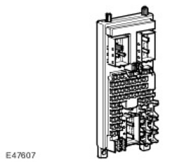
ECM (engine control unit) is connected to terminals I and II of the ignition switch. When the ignition key is turned to the ON position, 12 V is supplied to the ignition switch status sensor. The ECM then (engine control unit) starts power up routines and turns on the ECM power relay (engine control unit); power is supplied to the ECM (engine control unit) and devices of the systems associated with it. After turning off the ignition (oFF position) ECM (engine control unit) maintains power for 20 minutes while performing a shutdown procedure and then turns off the ECM power relay (engine control unit). ECM Disabling (engine control unit) typically occurs within 60 seconds. Do not disconnect the battery until the ECM has completely shut down. (engine control unit).
Comments on this article