Contents: Mounting box ⇩ Input signals ⇩ Output signals ⇩ ECM Wiring Harness Connector C0872…⇩ ECM Wiring Harness Connector C0411…⇩ ECM Wiring Harness Connector C2518…⇩ Blocking unauthorized launch ⇩
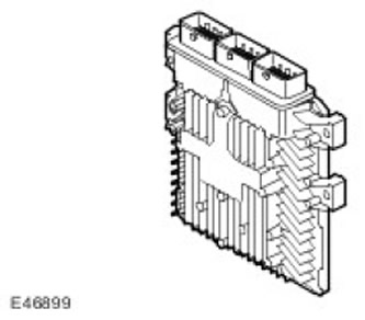
ECM (engine control unit) is located in the mounting box in the chamber on the right side of the engine compartment, fixed to the partition.
Mounting box
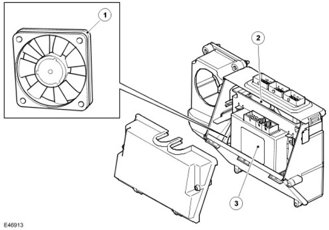
| Item name | Spare part catalog number | Description |
| 1 | Fan of the control system mounting box | |
| 2 | ECM (engine control unit) | |
| 3 | Transfer case controller |
Input signals
To the ECM input (engine control unit) the following signals are received:
The article was taken from this resource: LRMAN.RU
- Coolant temperatures
- Clutch switch (via the parking brake controller)
- Brake light switch (via ABS control unit) (anti-lock braking system) via CAN bus (local area network of controllers))
- Manifold Absolute Pressure
- Accelerator pedal positions 1
- Accelerator pedal positions 2
- Electronic throttle positions
- Viscous coupling fan speeds
- Engine Crankshaft Position and Speed Sensor (crankshaft sensor)
- Camshaft position sensor
- Engine oil temperatures
- Cruise control speed switches (resistive multi-link chains)
- Vehicle speeds (via CAN bus) (local area network of controllers))
- Generator control circuits
- Airbag and seat belt system module
- Manifold absolute pressure and intake air temperature
Output signals
ECM Block (engine control unit) generates output signals to control the following components and parameters:
- Throttle actuator
- Nozzles (6 pieces)
- EGR valves (exhaust gas recirculation systems)
- Cooling system fan
- Fuel pump relay
- Starter relay
- Air Conditioner Condenser Fan Module
- EMS power relay
- Control of the viscous clutch of the cooling system fan
- Generator control
To the ECM on-board network (engine control unit) connected via three connectors. In ECM (engine control unit) contains processors and memory microchips. Output signals for actuators are provided by grounding the circuits with ECM control circuits (engine control unit). ECM control circuits (engine control unit) during normal operation, they generate heat and dissipate it through the housing. A fan in the electronic box helps with the cooling process, maintaining a constant temperature in the box. The fan is controlled by a thermostat located in the junction box. The junction box is connected to the car's interior and receives additional cool air through the A/C system. Some sensors receive regulated voltage supplied by the ECM. (engine control unit). This measure allows to avoid signal distortion caused by voltage drop when the engine is cranked by the starter.
ECM (engine control unit) performs self-diagnostic routines and stores fault codes in memory. These fault codes and diagnostics can be accessed using the Land Rover approved diagnostic system. If the ECM (engine control unit) needs to be replaced, new ECM module (engine control unit) must be programmed using a Land Rover approved diagnostic system as it is supplied unprogrammed. EEPROM Electrically Erasable Programmable Read Only Memory (flash memory) using the Land Rover approved diagnostic system, allows the ECM configuration to be adjusted up to 14 times (engine control unit) in accordance with market specifics or new regulatory information. If the 15th software update is required, ECM (engine control unit) must be replaced. Current engine tuning parameter values can be retrieved and read using the Land Rover approved diagnostic system.
When installing a new ECM (engine control unit) it must also be synchronised with the anti-theft alarm control module using a Land Rover approved diagnostic system. The ECM must not be interchanged (engine control unit) different cars.
ECM (engine control unit) is connected to engine sensors that allow it to monitor the engine's operating mode. ECM (engine control unit) processes sensor signals and decides what actions need to be taken to maintain optimum engine performance in terms of overall vehicle drivability, fuel economy and emissions. In the ECM's memory (engine control unit) during programming, instructions are entered with an algorithm for controlling the engine, called a control strategy. In addition, the memory contains data in the form of special tables, on the basis of which the ECM (engine control unit) delivers fuel and reduces exhaust toxicity. By comparing information from sensors with data from ECM tables (engine control unit) is capable of generating requirements for the operation of various systems. ECM (engine control unit) contains an adaptive strategy that updates the system when its elements change due to manufacturing tolerances or aging.
ECM (engine control unit) receives vehicle speed signal via CAN bus (local area network of controllers) from ABS control module (anti-lock braking system)Vehicle speed is an important input signal for ECM strategies. (engine control unit). ABS control module (anti-lock braking system) determines the speed signal based on signals from the ABS wheel speed sensors (anti-lock braking system). The frequency of these signals depends on the driving speed. ECM (engine control unit) uses this signal to determine the following:
- How much to reduce engine torque when changing gears.
- When to enable speed control operation.
- To control the operation of the speed control system.
- Controlling idle speed when the vehicle is stationary.
ECM Wiring Harness Connector C0872 Pins
| Contact No. | Purpose | Input signal/output signal |
| A1 | Serial communication line with the immobilizer control unit | Output signal |
| A2 | Serial communication line with the immobilizer control unit | Input signal |
| A3 | CAN bus low level signal (local area network of controllers) | Input signal/output signal |
| A4 | CAN bus high level signal (local area network of controllers) | Input signal/output signal |
| B1 | Starter operation permission | Output signal |
| B2 | APP sensor mass (accelerator pedal position) | - |
| B3 | Radiator outlet temperature sensor mass | - |
| B4 | Cruise control | Input signal |
| C1 | APP sensor mass (accelerator pedal position) 1 | - |
| C2 | APP sensor reference voltage (accelerator pedal position) 2 | Output signal |
| C3 | ECT sensor (coolant temperature) | Output signal |
| C4 | Cruise control | Input signal |
| D1 | APP sensor signal (accelerator pedal position) 1 | Input signal |
| D2 | APP sensor mass (accelerator pedal position) 2 | - |
| D3 | Voltage 2 | Input signal |
| D4 | Not used | - |
| E1 | APP sensor reference voltage (accelerator pedal position) 1 | Output signal |
| E2 | Water in fuel sensor | Input signal |
| E3 | Brake switch 1 | Input signal |
| E4 | Inertia switch | Input signal |
| F1 | Intake Air Temperature Sensor | Input signal |
| F2 | Not used | - |
| F3 | Engine cranking signal | Input signal |
| F4 | Mass air flow sensor. | Input signal |
| G1 | Fuel pump supply control | Input signal |
| G2 | Brake light switch | Input signal |
| G3 | Not used | - |
| G4 | Not used | - |
| H1 | Not used | - |
| H2 | Not used | - |
| H3 | Not used | - |
| H4 | Not used | - |
| J1 | Not used | - |
| J2 | Fan of the control system mounting box | Output signal |
| J3 | Power relay | Output signal |
| J4 | Fuel pump relay | Output signal |
| K1 | Not used | - |
| K2 | Electric cooling fan control | Output signal |
| K3 | Sensor in the ignition switch | Input signal |
| K4 | Power in standby mode | Input signal |
| L1 | Battery voltage | Input signal |
| L2 | Battery voltage | Input signal |
| L3 | Battery voltage | Input signal |
| L4 | Weight | - |
| M1 | Weight | - |
| M2 | Weight | - |
| M3 | Weight | - |
| M4 | Weight | - |
ECM Wiring Harness Connector C0411 Pins
| Contact No. | Purpose | Input signal/output signal |
| A1 | Engine oil temperature sensor | Input signal |
| A2 | Not used | - |
| A3 | Not used | - |
| A4 | Not used | - |
| B1 | Backup analog input | Input signal |
| B2 | Backup analog input | Output signal |
| B3 | CAN bus low level signal (local area network of controllers) | Input signal/output signal |
| B4 | CAN bus high level signal (local area network of controllers) | Input signal/output signal |
| C1 | Not used | Input signal |
| C2 | Sensor mass | |
| C3 | Not used | |
| C4 | Knock sensor row B (-) | Input signal |
| D1 | Fuel rail pressure sensor signal | Input signal |
| D2 | Fuel Rail Pressure Sensor | Output signal |
| D3 | Knock sensor row B (+) | Output signal |
| D4 | Knock sensor row A (-) | Input signal |
| E1 | Throttle position sensor | Input signal |
| E2 | Fuel Rail Pressure Sensor Mass | - |
| E3 | Glow plug power supply control for row A | Input signal |
| E4 | Knock sensor row A (+) | Input signal |
| F1 | Electronic throttle voltage | Output signal |
| F2 | Electronic throttle body weight | - |
| F3 | Checking the glow plugs of row B | Input signal |
| F4 | Backup PWM output signal (pulse width modulation) | Output signal |
| G1 | Active Engine Suspension Control 1 | Output signal |
| G2 | Active Engine Suspension Control 2 | Output signal |
| G3 | Glow Plug Relay Control | Output signal |
| G4 | Not used | - |
| H1 | Generator Team | Output signal |
| H2 | Not used | - |
| H3 | Not used | - |
| H4 | Not used | - |
| J1 | Not used | - |
| J2 | Fan of the control system mounting box | |
| J3 | Power relay | Output signal |
| J4 | Fuel supply control valve | Output signal |
| K1 | Engine oil temperature sensor mass | - |
| K2 | Viscous Clutch Fan Control | Output signal |
| K3 | Fuel pressure control valve | Input signal |
| K4 | Intake Port Shut-Off Drive | Output signal |
| L1 | Injector command 1 | Output signal |
| L2 | Common Nozzle 1 | - |
| L3 | Common Nozzle 3 | - |
| L4 | Output signal | |
| M1 | Injector command 3 | Output signal |
| M2 | Injector command 5 | Output signal |
| M3 | Total Nozzle 5 | - |
| M4 | Mass 7 | - |
ECM Wiring Harness Connector C2518 Pins
| Contact No. | Purpose | Input signal/output signal |
| A1 | Backup analog input | - |
| A2 | EGR valve position sensor (exhaust gas recirculation systems) row B | Input signal |
| A3 | EGR valve position sensor (exhaust gas recirculation systems) row A | Input signal/output signal |
| A4 | Not used | Input signal/output signal |
| B1 | Charge air temperature sensor | Input signal |
| B2 | Fuel temperature sensor | Input signal |
| B3 | Not used | - |
| B4 | Not used | - |
| C1 | Manifold Absolute Pressure Sensor | Input signal |
| C2 | Engine Coolant Temperature Sensor | - |
| C3 | Analog voltage 1 | Input signal |
| C4 | VGT row A | Input signal |
| D1 | Supply for the absolute pressure sensor in the manifold | Output signal |
| D2 | Sensor mass M | Output signal |
| D3 | Not used | |
| D4 | Not used | |
| E1 | Engine cooling system fan control device | Input signal |
| E2 | Not used | - |
| E3 | Not used | - |
| E4 | Not used | - |
| F1 | Crankshaft position sensor | Input signal |
| F2 | Generator load sensor signal | Input signal |
| F3 | Not used | - |
| F4 | Not used | - |
| G1 | Power supply for crankshaft position sensor | Output signal |
| G2 | Crankshaft Position Sensor Mass | - |
| G3 | Variable Geometry Turbine Drive Mass | - |
| G4 | Camshaft sensor signal | Input signal |
| H1 | EGR (exhaust gas recirculation systems) row A (+) | Output signal |
| H2 | EGR (exhaust gas recirculation systems) row A (-) | - |
| H3 | Camshaft Position Sensor Mass | - |
| H4 | Power supply for the camshaft position sensor | Output signal |
| J1 | EGR (exhaust gas recirculation systems) row B (+) | Output signal |
| J2 | VGT row A (+) | Output signal |
| J3 | Not used | Output signal |
| J4 | Throttle actuator (+) | Output signal |
| K1 | EGR (exhaust gas recirculation systems) row B (-) | - |
| K2 | VGT (-) | - |
| K3 | Not used | Input signal |
| K4 | Throttle actuator (-) | - |
| L1 | Not used | - |
| L2 | Common injector 2 | - |
| L3 | Total injector 0 | - |
| L4 | Common injector 4 | - |
| M1 | Power circuit mass | - |
| M2 | Injector command 2 | Output signal |
| M3 | Injector command 0 | Output signal |
| M4 | Injector command 4 | Output signal |
Blocking unauthorized launch
The IMMOBILIZER control unit receives data from the relevant vehicle systems and transmits a coded signal to the ECM (engine control unit) to allow the engine to start if all conditions for this are met. The data is decoded by the ECM (engine control unit), and if they are correct, the engine starts.
The data is a continuously changing code, so the immobilizer control unit and ECM (engine control unit) must be synchronized in case of replacement of any of the devices.
In addition, ECM (engine control unit) protects the starter from accidental activation. The IMMOBILIZER control unit receives the engine crankshaft speed signal from the ECM via the instrument cluster (engine control unit). If the engine speed exceeds a preset value, the immobilizer control unit prohibits the starter operation via the built-in starter interlock relay. For more information, refer to AntiTheft - Passive (419-01B Anti-Theft - Passive)
Comments on this article