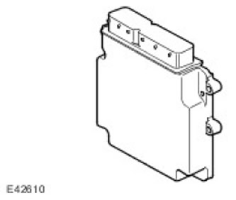
ECM (the engine control unit) located in a mounting box in the engine compartment chamber on the passenger side, fixed to the bulkhead.
Incoming Signals
To ECM input (the engine control unit) the following signals are received:
- Central switching unit
- Coolant temperature
- brake switch
- Manifold absolute pressure
- Accelerator pedal position 1
- Accelerator pedal position 2
- Throttle position 1
- Throttle position 2
- Engine cooling system fan speed
- Position and engine speed sensor (crankshaft sensor)
- Camshaft position sensor
- Engine oil temperature
- IAT sensor (intake air temperature) (built into MAF (mass air flow))
- MAF (mass air flow)
- knock sensors (2)
- Cruise Control Speed Switches (resistive ladder chains)
- oxygen sensors (4)
- Vehicle speed (via CAN bus (local area network of controllers))
- Differential pressure eGr (exhaust gas recirculation)
- EGR (exhaust gas recirculation) mAp (manifold absolute pressure)
- Generator control circuits
Output signals
ECM block (the engine control unit) generates output signals to control the following components and parameters:
- Throttle actuator
- Ignition coils (6)
- Oxygen sensor heaters (4)
- fuel injectors (6)
- EGR valve (exhaust gas recirculation)
- IMT valve (intake manifold adjustment)
- Purge valve
- Fuel pump relay
- Starter relay
- A/C Condenser Fan Module (CAN (local area network of controllers))
- EMS Power Relay
- Control of the viscous coupling of the fan of the cooling system
- Generator control
ECM Management Strategy (the engine control unit) is based on the amount of torque requested by the driver and various vehicle ECUs. The EMS uses various sensors to determine the amount of torque that an engine needs to produce. These include:
- Mass air flow sensor
- Accelerator pedal position sensor
- Engine temperature sensors
- oxygen sensors
- ABS control unit (anti-lock braking system)
- TCM (transmission control unit)
- Transfer box controller
| contact no | Purpose | Input signal / output signal |
| 1 | CAN (local area network of controllers) | Input signal / output signal |
| 2 | CAN (local area network of controllers) | Input signal / output signal |
| 3 | Determining the state of the generator | Input signal |
| 4 | Weight UHEGO row A | - |
| 5 | Weight UHEGO series B | - |
| 6 | - engine start sensor | Input signal |
| 7 | Camshaft sensor weight | - |
| 8 | Not used | - |
| 9 | Not used | - |
| 10 | Sensor weight 3 | - |
| 11 | Sensor weight 4 | - |
| 12 | Sensor weight 5 | - |
| 13 | Not used | - |
| 14 | Reserve weight | - |
| 15 | Sensor weight 6 | - |
| 16 | Not used | - |
| 17 | Not used | - |
| 18 | Mass MAF (mass air flow) | - |
| 19 | Bank A knock sensor ground | - |
| 20 | Bank B knock sensor ground | - |
| 21 | Not used | - |
| 22 | Not used | - |
| 23 | Oil temperature sensor | Input signal |
| 24 | Sensor power supply 6 | Output signal |
| 25 | LIN A | Output signal |
| 26 | UHEGO Series B (+) | Input signal |
| 27 | UHEGO Series B (-) | - |
| 28 | UHEGO series A (+) | + |
| 29 | UHEGO series A (-) | - |
| 30 | + engine start sensor | Input signal |
| 31 | Not used | - |
| 32 | Not used | - |
| 33 | Not used | - |
| 34 | CMP sensor signal (camshaft position) row A | Input signal |
| 35 | Not used | - |
| 36 | Not used | - |
| 37 | Not used | - |
| 38 | Differential pressure sensor | Input signal |
| 39 | Not used | - |
| 40 | Fuel pressure sensor | Input signal |
| 41 | Not used | - |
| 42 | Bank A knock sensor (+) | Input signal |
| 43 | Bank B knock sensor (+) | Input signal |
| 44 | Not used | - |
| 45 | Not used | - |
| 46 | Fuel temperature sensor | Input signal |
| 47 | Sensor power supply 5 | Output signal |
| 48 | Sensor power supply 4 | Output signal |
| 49 | Not used | - |
| 50 | Not used | - |
| 51 | Not used | - |
| 52 | Not used | - |
| 53 | Not used | - |
| 54 | Not used | - |
| 55 | Not used | - |
| 56 | Cylinder 3 B ignition coil | Output signal |
| 57 | Cylinder coil 3 A | Output signal |
| 58 | Cylinder 2 B ignition coil | Output signal |
| 59 | Ignition coil cylinder 2 A | Output signal |
| 60 | Ignition coil cylinder 1 B | Output signal |
| 61 | Cylinder coil 1 A | Output signal |
| 62 | Bank A ignition coil weight | - |
| 63 | Viscous fan control circuit | Input signal |
| 64 | Bank B ignition coil weight | - |
| 65 | Throttle position sensor 1 | -I |
| 66 | Air temperature sensor | Input signal |
| 67 | Throttle position sensor 2 | Input signal |
| 68 | coolant temperature sensor | Input signal |
| 69 | MAP (manifold absolute pressure) | Input signal |
| 70 | MAF (mass air flow) | Input signal |
| 71 | Not used | - |
| 72 | Sensor power supply 3 | Output signal |
| 73 | Not used | - |
| 74 | throttle direction (-) | Output signal |
| 75 | throttle direction (+) | Output signal |
| 76 | UHEGO heater row A | Output signal |
| 77 | Row B UHEGO heater | Output signal |
| 78 | Nozzle cylinder 1 B | Output signal |
| 79 | Nozzle cylinder 1 B | Output signal |
| 80 | Nozzle cylinder 2 A | Output signal |
| 81 | Nozzle cylinder 2 B | Output signal |
| 82 | Cylinder nozzle 3 A | Output signal |
| 83 | Nozzle cylinder 3 B | Output signal |
| 84 | Intake manifold control valve 1 | Output signal |
| 85 | Not used | - |
| 86 | Not used | Output signal |
| 87 | Not used | Output signal |
| 88 | Not used | Output signal |
| 89 | Not used | - |
| 90 | EGR (exhaust gas recirculation) | Input signal |
| 91 | Not used | - |
| 92 | Purge valve | Output signal |
| 93 | Cooling fan viscous clutch adjustment request | Output signal |
| 94 | Not used | - |
| 95 | Fuel pump relay | Output signal |
| 96 | Generator control | Output signal |
C0635 ECM Connector Pin Chart
| contact no | Purpose | Input signal / output signal |
| 1 | Signal mass 1 | - |
| 2 | Force Mass 1 | - |
| 3 | Force Mass 2 | - |
| 4 | ECM Power (the engine control unit) | Input signal |
| 5 | Force Mass 3 | - |
| 6 | APP sensor weight (accelerator pedal position) 1 | - |
| 7 | APP sensor weight (accelerator pedal position) 2 | - |
| 8 | Not used | - |
| 9 | Not used | - |
| 10 | Not used | - |
| 11 | Not used | - |
| 12 | Park/neutral position signal | Input signal |
| 13 | Not used | - |
| 14 | Not used | - |
| 15 | Not used | - |
| 16 | EMS relay | Output signal |
| 17 | crankshaft request | Output signal |
| 18 | + CAN bus (local area network of controllers) | Output signal |
| 19 | Sensor power 2 APP (accelerator pedal position) | Output signal |
| 20 | Fuel pump control | Output signal |
| 21 | Not used | - |
| 22 | Not used | - |
| 23 | Not used | - |
| 24 | APP sensor signal (accelerator pedal position) 1 | Output signal |
| 25 | ||
| 26 | Stoplight switch | Input signal |
| 27 | Not used | - |
| 28 | Not used | - |
| 29 | Not used | - |
| 30 | ignition switch | Input signal |
| 31 | + CAN bus (local area network of controllers) | Input signal |
| 32 | Sensor Power 1 APP (accelerator pedal position) | Output signal |
| 33 | DMTL | Output signal |
| 34 | Not used | - |
| 35 | - speed switch | Output signal |
Electronic Throttle
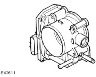
The V6 engine's torque is controlled in the throttle body, which is located on the intake manifold in the engine bay. APP sensor (accelerator pedal position) registers the driver's command to change the throttle position. This signal is input to the ECM and the throttle valve is opened by a motor built into the throttle body to change the angle. A sensor in the throttle body determines the position of the throttle and the rate of change of its angle of rotation. ECM Software (the engine control unit) provides for the calibration of the damper position in each ignition cycle. When the ignition is turned on (ON position), ECM (the engine control unit) fully opens and closes the throttle, thereby performing self-diagnosis and calibration. Throttle body to attenuate electrical noise connected to ECM (the engine control unit) with a pair of twisted wires. For more information refer to Acceleration Control (310-02A)
Throttle connector pin chart C0175
| contact no | Purpose | Input signal / output signal |
| 1 | Signal 1 | Output signal |
| 2 | Power supply 5 V | Input signal |
| 3 | Signal 2 | Output signal |
| 4 | Weight | - |
| 5 | + drive | Input signal |
| 6 | - drive | - |
Comments on this article