Contents: Fuel Pump Relay ⇩ Viscous Clutch Fan Control ⇩ Variable Valve Timing (VVT) ⇩ VVT mechanism clutch ⇩ Phase control electromagnetic valve ⇩ Exhaust Gas Recirculation (EGR) Valve ⇩
Fuel Pump Relay
The V8 engine uses a closed fuel supply system. Regardless of the pressure in the intake manifold, a constant fuel pressure of 4 bar is maintained in the fuel system. Fuel is supplied to the injectors by a fuel pump located in the fuel tank. Power is supplied to the fuel pump under the control of the ECM (engine control unit) via a power relay and an inertia switch that shuts off the fuel supply in the event of a collision. The fuel system is pressurized immediately after the ECM is powered up. (engine control unit), then the fuel pump is switched off until the engine starts.
Viscous Clutch Fan Control
ECM Block (engine control unit) regulates engine cooling by controlling the viscous fan. To regulate the fan performance, the ECM (engine control unit) uses PWM (pulse width modulation) -signals, controlling the clutch slip ratio. The EMS detects the fan speed using a Hall effect sensor. For more information, please refer to Engine Cooling (303-03B Engine Cooling - 4.4L)
Variable Valve Timing (VVT)
To improve engine performance in the low and high speed ranges and to increase idle stability, the engine uses variable valve timing.
The mechanism for adjusting the phases of one intake camshaft consists of the following components:
- VVT mechanism clutch
- Phase control electromagnetic valve
The VVT system varies the timing of the intake valves in relation to the fixed timing of the exhaust valves in order to control:
- Weight filling of engine cylinders.
- Engine torque.
- Toxicity of OG.
A hydraulic paddle clutch is used to change the angular position of the camshaft. The angular position of the shaft can be changed in the range of 48 degrees. The phases of the shaft change towards delay or advance, taking the optimal value in the specified range.
ECM Block (engine control unit) controls the VVT system based on engine load, crankshaft speed and engine oil temperature.
Using the VVT system provides the following advantages:
- Reduced toxicity of exhaust gases and reduced fuel consumption, which in turn increases the efficiency of internal exhaust gas recirculation EGR (exhaust gas recirculation) over a wider range of engine operation.
- Improved external torque characteristic.
- Reduced fuel consumption due to improved torque characteristics across the entire speed range.
VVT mechanism clutch
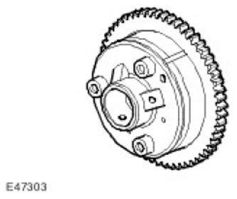
To control the position of the intake camshaft, a hydraulic clutch is used, mounted on its nose. The clutch moves the camshaft forward or backward in relation to the crankshaft. To control the VVT clutch, the ECM (engine control unit) uses a solenoid hydraulic valve. The solenoid valve is a spool type and directs pressurized oil to either the advance or retard chambers of the clutch.
The VVT clutch is driven by the primary timing chain and can change its position relative to the exhaust camshaft. When the ECM (engine control unit) requires a reduction in the advance of the camshaft phases, the electromagnetic valve is activated, moving the spool to a position in which the oil leaves the advance chambers and at the same time the oil under pressure enters the retard chambers.
ECM Block (engine control unit) adjusts the advance or retardation of the shaft based on engine load and crankshaft speed. ECM (engine control unit) maintains the supply of power to the solenoid valve until the camshaft reaches the set position. When the camshaft reaches the set position, the supply to the valve is limited to the level of maintaining the achieved position. This process occurs in the closed-loop control mode, when the ECM (engine control unit) "learns" about all changes in oil pressure in the spool valve using signals from the camshaft position sensor and regulates the power supply to the electromagnet to maintain the set position.
The operation of the VVT mechanism is affected by the oil temperature and its properties. At low oil temperature, due to its high viscosity, the VVT mechanism will slowly adjust the shaft position. At high oil temperature, the performance of the VVT mechanism can be negatively affected by a decrease in oil viscosity. The oil pump capacity is large enough to counteract changes in oil properties, and the oil temperature sensor constantly informs the ECM (engine control unit) data for the necessary correction. At extremely high ECM oil temperature (engine control unit) can impose a limit on the phase advance value so that the engine does not stall when switching to idle mode.
The VVT mechanism stops working if the oil pressure does not exceed 1.25 bar. This is because the pressure is not high enough to release the VVT clutch from the internal locking pin. This happens when the engine is switched off and the clutch returns to the most retarded position. The locking pin fixes the position of the clutch so that the camshaft remains stable during the next start. For more information, refer to Engine (303-01B Engine - 4.4L)
Phase control electromagnetic valve
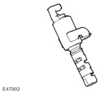
The solenoid valve for phase control controls the position of the spool relative to the sleeve. The solenoid valve stem extends when the power is turned on and retracts when the power is turned off.
When the solenoids are de-energized, coil springs in the sleeves hold the spools in the position to drain oil from the hydraulic clutches. Return springs located in the hydraulic clutches hold the camshafts in the retarded position. When the ECM (engine control unit) supplies power to the electromagnetic valves, their rods set the spools to the position of supplying engine oil to the hydraulic clutches. The oil pressure overcomes the resistance of the return springs in the clutches and moves the annular piston in the advance direction. The system reaches the advance position in no more than 1.0 s, and the retard position in no more than 0.7 s. When the clutches are in the retard position, the ECM (engine control unit) periodically gives the order to perform lubrication. In this case, a short power pulse is sent to the electromagnetic valve, which causes a short injection of oil into the clutch. Such pulsating lubrication is performed once every five minutes.
Exhaust Gas Recirculation (EGR) Valve
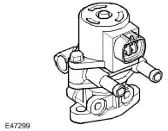
EGR valve (exhaust gas recirculation) is an electrically controlled valve that is designed to bypass exhaust gases back into the engine. EGR valve (exhaust gas recirculation) opens and closes using a stepper motor. Since the exhaust gases contain very little free oxygen, they are virtually inert. The exhaust gases take the place of air in the combustion chamber, which reduces the maximum combustion temperature. A decrease in the maximum combustion temperature leads to a decrease in the formation of nitrogen oxides (NOx).
EGR valve (exhaust gas recirculation) is located on the intake manifold and is connected by a tube to the exhaust manifold. The connection to the wiring harness is made through a 6-pin connector. For more information, refer to Engine Emission Control (303-08B)
Comments on this article