car logo Ford
car logo Volkswagen
car logo BMW
car logo Opel
car logo Audi
car logo Toyota
car logo Peugeot
English Русский
Български
Беларускі
Український
Српски
Hrvatski
Română
Polski
Slovenský
Magyar


Main
Freelander
Discovery
Range Rover
Defender
Contacts
Articles

Mounting box and power supply 4.0L (Discovery 3)

 
  • Main
  • Discovery
  • Discovery 3
  • Power unit
  • Electronic control part
  • Mounting box and power supply 4.0L
 
        0  
Contents: Central mounting box ⇩ Power supply ⇩ Purge valve ⇩

Central mounting box


The central junction box is used to initiate power on and off programs in the ECM. (engine control unit). When the ignition is turned on, the ignition switch status sensor input (contact 30 of connector C0635) 12V voltage is applied. Then the ECM (engine control unit) starts power up routines and turns on the ECM power relay (engine control unit).

After turning off the ignition (oFF position) ECM (engine control unit) maintains power for several seconds (in extreme cases, if necessary for the cooling system fans, this can continue for 20 minutes), performing the shutdown procedure, and then turns off the ECM power relay (engine control unit).

Power supply


For the operation of the ECM unit (engine control unit) requires a continuous supply of battery supply voltage as well as a commanded supply of battery supply voltage. The commanded supply voltage is supplied through a relay controlled by the ECM (engine control unit), based on the state at the input of the central switching unit (key position 2).

In the "OFF" position of the ECM key (engine control unit) keeps the supply voltage on until the internal self-diagnosis is completed. The main supply fuse is located in the engine compartment fuse box.

Purge valve


Hoses and purge valve
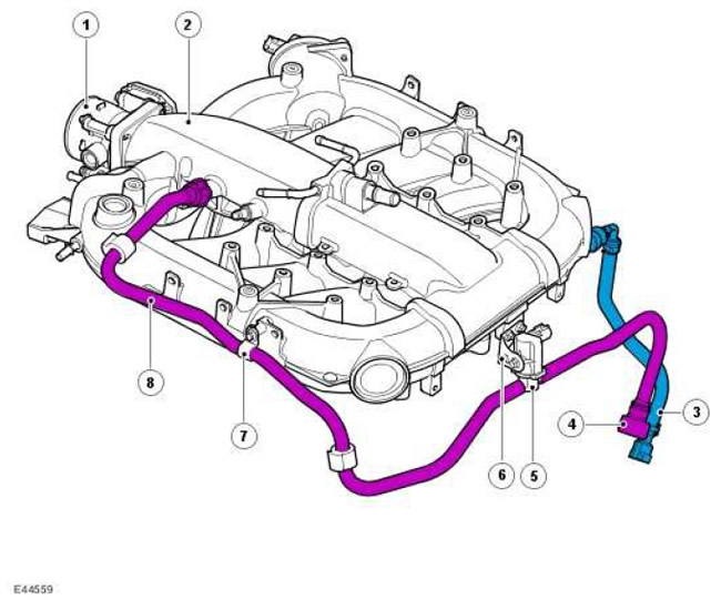

Hoses and purge valve


Item nameSpare part catalog numberDescription
1-Electronic throttle
2-Air intake manifold
3-Fuel supply pipe
4-Blow-off hose nipple
5-Purge valve
6-Blow off valve bracket
7-Hose clamp
8-Hose connecting the manifold to the purge valve


To meet increasingly stringent fuel vapor regulations, the vehicle uses a fuel vapor recovery system that minimizes losses from the evaporation of fuel vapor from the fuel system into the atmosphere. This is achieved by removing gases from the fuel system through a vapor trap. (carbon adsorber)The carbon acts as a sponge and traps the vapors until the canister is purged under the control of the ECM. (engine control unit).

The carbon canister is connected to the intake manifold behind the throttle body via a purge valve. The state of this valve changes according to the PWM. (pulse width modulation) - signal transmitted by the ECM unit (engine control unit). The adsorber is purged by pumping clean air through the carbon, which carries the hydrocarbons into the engine, where they are burned. To maintain controllability and reduce exhaust toxicity, the purging process must be fully controlled, since even 1% of fuel vapor from the adsorber entering the air intake can lead to a 20% change in the composition of the working mixture. Since the accumulation capacity of the carbon is limited, purging to restore its condition must be performed regularly, alternating with fuel supply correction, since both operations cannot be performed simultaneously.

ECM (engine control unit) via PWM (pulse width modulation) - the signal controls the purge valve, regulating the intensity of the purge of the adsorber. Control of the purge process allows maintaining the stoichiometric composition of the working mixture necessary for the correct operation of the engine. In addition, due to this, the purge of the adsorber is performed quite often, thereby preventing the saturation of the coal with fuel, leading to excessive accumulation of fuel vapors in the system (and therefore to an increase in vapor pressure) and, as a result, to an increased likelihood of vapor leakage. For more information, refer to Evaporative Emissions (303-13A)


This article is available at russian, bulgarian, belarusian, ukrainian, serbian, croatian, romanian, polish, slovak, hungarian
Article review: Saveliy Ushakov


Previous articles
Specification 4.0L
Specification 4.4L
Specification 2.7L
Device and technical description 4.0L
Engine Control Module (ECM) 4.0L
Accelerator Pedal Position Sensor (APP) 4.0L
Oxygen Sensors 4.0L
Knock Sensors 4.0L

Current article
Mounting box and power supply 4.0L

Next articles
Device and technical description 4.4L
Engine Control Module (ECM) 4.4L
Shaft Position and Temperature Sensors 4.4L
Knock Sensors 4.4L
Electronically controlled throttle 4.4L
Accelerator Pedal Position Sensor (APP) 4.4L
Oxygen sensors 4.4L
Generator, injectors and ignition 4.4L


Similar articles from Land Rover repair manuals:
• Siren with autonomous power supply (if available) Freelander 2 (2006-2014)
• Power supply element for the alarm system control panel Freelander 1 (1997-2006)
• Engine power supply system Range Rover 3 (2001-2012)
• Filling and bleeding the power steering system Defender 2007+ (2007-2016)

Comments on this article


No comments yet


How much will 20 + 34 =


Discovery 3 
  • General information
  • Using the manual
  • Precautionary measures
  • Service Information
  • Technique
  • Health protection
  • Road test
  • Identification codes
  • Jacking and lifting
  • Maintenance - diesel
  • Maintenance - petrol
  • Chassis
  • Suspension
  • Front suspension
  • Rear suspension
  • Wheels and tires
  • Dynamic suspension
  • Cardan shaft
  • Rear drive axle
  • Front drive axle
  • Front axle axles
  • Rear axle axles
  • Brake system
  • Parking brake
  • Hydraulic brake
  • Vacuum brake booster
  • Anti-lock braking system
  • Steering
  • Steering column
  • Power unit
  • Petrol engine 4.0L
  • Petrol engine 4.4L
  • Diesel engine 2.7L
  • Engine cooling
  • Fuel supply
  • Drive units
  • Launch system
  • Ignition system
  • Emission reduction
  • Air filtration
  • Fuel vapor control
  • Electronic control part
  • Car gearbox
  • Clutch
  • All-wheel drive systems
  • Transfer case
  • Exhaust system
  • Fuel tank and lines
  • Acceleration control
  • Electrical equipment
  • Climate control
  • Instruments and control lamps
  • Battery and charging system
  • Information system
  • Lighting and headlights
  • Power distribution
  • Electronic Function Group
  • Body and coating
  • Body elements
  • Interior and body trim
  • Mirrors and glasses
  • Seats
  • Instrument panel and console
  • Handles and locks
  • Windshield wipers and washers
  • Sunroof and bumpers
  • Safety system
  • Body repairs
  • Repair of front end elements
  • Repair of back elements
  • Side panel repair
  • Frame and body mount

Discovery 1 
  • General information
  • Technical specifications
  • Introduction to manual
  • Troubleshooting
  • Power unit
  • Diesel engine Tdi
  • Petrol engine V8i (3.9 l)
  • Petrol engine V8i (4.0 l)
  • Petrol engine Mpi
  • Reducing harmful emissions
  • Fuel system Tdi
  • Fuel system MFi
  • Fuel system SFi
  • Fuel system MPi (MEMS)
  • Cruise control
  • Cooling system (Tdi)
  • Cooling system (V8i)
  • Cooling system (MPi)
  • Exhaust system
  • Transmission
  • Clutch
  • Manual gearbox R380
  • Manual gearbox LT 77
  • Transfer case LT230T
  • Automatic gearbox
  • Cardan shaft
  • Rear axle
  • Front axle
  • Chassis
  • Steering system
  • Front suspension
  • Rear suspension
  • Brake system
  • Wheels and tires
  • Body and interior
  • Passive safety
  • Doors, locks and windows
  • Exterior body parts
  • Interior trim details
  • Seats
  • Electrical equipment
  • Heating and ventilation
  • Air conditioning
  • Windscreen wipers
  • Starting and charging system
  • Equipment and devices
  • Lighting and headlights


LRman.ru © 2013-2026 | Mobile version | Free Lander | Discovery | Range Rover | Defender | Contacts | | Sitemap |
Car repair and service instructions Land Rover: Freelander, Discovery, Range Rover, Defender
We use cookies to make pages load faster and provide a more user-friendly experience 🍪