Generator
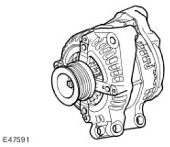
The generator has a multifunctional charging voltage regulator (14 V) and a zener diode rectifier.
ECM (the engine control unit) controls the load of the electrical system by PWM (pulse width modulation) -signals and and regulates the output power of the generator in accordance with the specified load. In addition, ECM (the engine control unit) monitors the battery temperature to determine the generator regulator setpoint. This parameter is needed to protect the battery from damage. At low battery temperatures, its charging capacity is extremely low, and to compensate for this circumstance, it is necessary to increase the charging voltage as much as possible, however, at high temperatures, the charging voltage must be reduced to prevent excessive gas formation and, as a result, loss of water from the electrolyte.
The generator circuit contains intelligent controls that reduce the load on the generator if there is a need to maximize the use of engine torque for other purposes. For such control, three signals are used that come to the ECM (the engine control unit):
- Alternator sensor A measures voltage at CJB (central junction box).
- Generator communication system (Alt Com) transmits the generator voltage setting from the ECM (the engine control unit) into the generator.
- Generator status sensor (Alt Mon) sends to ECM (the engine control unit) current value in the generator load circuit. In the same data package in eCm (the engine control unit) fault signals are sent. Based on received CAN·messages (the engine control unit) sends a request to the instrument panel to turn on the charging circuit warning light. For more information refer to Generator (414-02B Generator and Regulator - 4.4L)
Nozzles
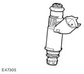
There is one injector for each cylinder of the engine (total 8). Each injector is directly controlled by the ECM (the engine control unit). The injectors are powered from the fuel rail. The injector power circuit is part of a closed power system («isolation» means no backflow in a certain part of the power system). A fuel pressure regulator built into the fuel priming pump located in the fuel tank maintains a pressure of 4.5 bar in the fuel rail. The serviceability of the injectors is checked by measuring the resistance of the electromagnet winding. To check the pressure in the fuel system, a Schrader valve is mounted on the left front side of the fuel rail. eCm (the engine control unit) monitors the circuits of the output stages of the injector drive units for electrical faults.
Injector resistance at 20 degrees Celsius should be 13.8 +/- 0.7 ohms Refer to Fuel Charging and Controls for more information (303-04B Fuel Charging and Controls - 4.4L)
Ignition coils
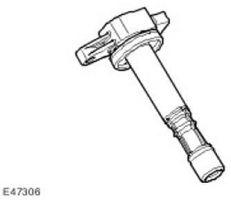
The V8 engine has 8 individual top entry ignition coils controlled directly by the ECM (the engine control unit) . This means that when a sufficient level of inductive charging of the ECM coil is reached (the engine control unit) breaks the circuit of the primary winding of the coil, and a spark forms between the electrodes of the spark plug. Innings «positive» voltage to the coil is produced from a common fuse. Each coil has a power transistor that controls the on and off of the primary winding. To turn on the power circuit of each ECM coil (the engine control unit) sends a control signal. The power circuit of the ignition coils provides the formation of a feedback signal. If a fault occurs in the power circuit of the ignition coil, the feedback signal is lost and the ECM (the engine control unit) records the fault code of the corresponding fault.
To ensure the constancy of the discharge energy on the electrodes of the ECM spark plug (the engine control unit) calculates the period of the closed state of the primary winding based on the voltage of the battery and the speed of the crankshaft. This ensures sufficient discharge energy without overloading the primary winding with the possibility of overheating or damage.
Ignition timing (sparking) on each cylinder is determined by the value of several input parameters:
- Engine load and crankshaft speed.
- Coolant temperature.
- Information from knock sensors.
- Information from the automatic transmission controller.
- Information from the idle control system.
For more information refer to Engine Ignition (303-07B)
Comments on this article