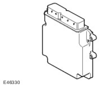
ECM (the engine control unit) located in the mounting box in the chamber on the left side of the engine compartment, mounted on the bulkhead.
ECM block (the engine control unit) accepts input signals from the following components and according to the following parameters:
- Fuel supply to the engine.
- Distribution of ignition points.
- Closed-loop refueling.
- Detonation management.
- Idle adjustment
- Decrease in exhaust toxicity.
- Onboard diagnostics.
- Providing an interface with the anti-theft system
ECM block (the engine control unit) generates output signals to control the following components and parameters:
- Throttle actuator
- Ignition coils (8 pieces)
- Oxygen sensor heaters (4 pieces)
- nozzles (8 pieces)
- EGR stepper motor (exhaust gas recirculation)
- Valves of the mechanism of change of phases of gas distribution (2)
- Purge valve
- Cooling fan
- Fuel pump relay
- Starter relay
- A/C Condenser Fan Module
- EMS Power Relay
- Control of the viscous coupling of the fan of the cooling system
- Generator control
- Power Steering
- Fuel tank leak control module (DMTL) (only for NAS vehicles)
C0634 ECM Connector Pin Chart
| contact no | Purpose | Input signal / output signal |
| 1 | CAN (controller LAN) | Input signal / output signal |
| 2 | CAN (controller LAN) | Input signal / output signal |
| 3 | Determining the state of the generator | Input signal |
| 4 | Weight UHEGO row A | - |
| 5 | Weight UHEGO series B | - |
| 6 | Not used | - |
| 7 | Not used | - |
| 8 | Not used | - |
| 9 | Not used | - |
| 10 | Not used | - |
| 11 | Weight CKP (crankshaft position) | - |
| 12 | Weight row A of the CMP sensor (crankshaft position) | - |
| 13 | Mass of bank B of the CMP sensor (crankshaft position) | - |
| 14 | Cylinder bank UHEGO sensor signal | Input signal |
| 15 | Weight of electronic throttle | - |
| 16 | Mass MAF (mass air flow) | - |
| 17 | Weight of HEGO | - |
| 18 | Not used | - |
| 19 | Ground knock sensor 1 | - |
| 20 | Ground knock sensor 2 | - |
| 21 | Ground knock sensor 3 | - |
| 22 | Ground knock sensor 4 | - |
| 23 | Power 5V Electronic Throttle Body | Output signal |
| 24 | Fuel pump relay | Output signal |
| 25 | Not used | - |
| 26 | Not used | - |
| 27 | Not used | - |
| 28 | Not used | - |
| 29 | Radiator temperature sensor | Input signal |
| 30 | Engine Start Sensor Signal | Input signal |
| 31 | Not used | - |
| 32 | Not used | - |
| 33 | CMP sensor signal (crankshaft position) row B | Input signal |
| 34 | CMP sensor signal (crankshaft position) row A | Input signal |
| 35 | Not used | - |
| 36 | Bank A UHEGO sensor signal | Input signal |
| 37 | Bank A UHEGO sensor signal ground | - |
| 38 | Bank B UHEGO sensor signal ground | - |
| 39 | Fuel temperature sensor | Input signal |
| 40 | Fuel pressure sensor | Input signal |
| 41 | Not used | Input signal |
| 42 | Not used | Input signal |
| 43 | Knock sensor 1 + | Output signal |
| 44 | Knock sensor 2+ | Output signal |
| 45 | Knock sensor 3+ | Output signal |
| 46 | Knock sensor 4+ | Output signal |
| 47 | Generator control | Output signal |
| 48 | Control junction box fan | Output signal |
| 49 | Not used | - |
| 50 | EGR stepper motor (exhaust gas recirculation) 4 | Output signal |
| 51 | EGR stepper motor (exhaust gas recirculation) 3 | Output signal |
| 52 | EGR stepper motor (exhaust gas recirculation) 2 | Output signal |
| 53 | EGR stepper motor (exhaust gas recirculation) 1 | Output signal |
| 54 | Cylinder 4 B ignition coil | Output signal |
| 55 | Cylinder ignition coil 4 A | Output signal |
| 56 | Cylinder 3 B ignition coil | Output signal |
| 57 | Not used | - |
| 58 | Not used | - |
| 59 | Not used | - |
| 60 | Not used | - |
| 61 | Not used | - |
| 62 | Not used | - |
| 63 | Not used | - |
| 64 | Not used | - |
| 65 | Not used | - |
| 66 | Not used | - |
| 67 | Not used | - |
| 68 | Not used | - |
| 69 | Not used | - |
| 70 | MAF (mass air flow) | Input signal |
| 71 | Purge valve | Output signal |
| 72 | - starter relay | - |
| 73 | Throttle Body Power | Output signal |
| 74 | direction "-" throttle turn | Output signal |
| 75 | direction "+" throttle turn | Output signal |
| 76 | UHEGO heater bank A cylinders | Output signal |
| 77 | UHEGO heater bank B | Output signal |
| 78 | Cylinder injector 4B | Output signal |
| 79 | Cylinder nozzle 4A | Output signal |
| 80 | Cylinder injector 3B | Output signal |
| 81 | Cylinder nozzle 3A | Output signal |
| 82 | Nozzle cylinder 2B | Output signal |
| 83 | Nozzle cylinder 2A | Output signal |
| 84 | Nozzle cylinder 1B | Output signal |
| 85 | Cylinder nozzle 1A | Output signal |
| 86 | VVT row A | Output signal |
| 87 | VVT row B | Output signal |
| 88 | Viscous fan control | Output signal |
| 89 | Not used | - |
| 90 | Oil temperature sensor | Input signal |
| 91 | Throttle body tell-tale | Input signal |
| 92 | + starter relay | Output signal |
| 93 | Not used | - |
| 94 | Cooling fan viscous clutch adjustment request | Input signal |
| 95 | Purge valve | Output signal |
C0635 ECM Connector Pin Chart
| contact no | Purpose | Input signal / output signal |
| 1 | Signal mass 1 | - |
| 2 | Force Mass 1 | - |
| 3 | Force Mass 3 | - |
| 4 | Force Mass 2 | - |
| 5 | ECM Power (the engine control unit) | Input signal |
| 6 | APP sensor weight (accelerator pedal position sensor) 1 | - |
| 7 | APP sensor weight (accelerator pedal position sensor) 2 | - |
| 8 | Not used | - |
| 9 | Not used | - |
| 10 | Not used | - |
| 11 | Not used | - |
| 12 | Park/neutral position signal | Input signal |
| 13 | Not used | - |
| 14 | Not used | - |
| 15 | Not used | - |
| 16 | EMS relay | Output signal |
| 17 | crankshaft request | Output signal |
| 18 | + CAN bus (controller LAN) | Output signal |
| 19 | Sensor power 2 APP (accelerator pedal position sensor) | Output signal |
| 20 | Fuel pump control system | Output signal |
| 21 | Not used | - |
| 22 | Not used | - |
| 23 | Not used | - |
| 24 | APP sensor signal (accelerator pedal position sensor) 1 | Output signal |
| 25 | Not used | - |
| 26 | Stoplight switch | Input signal |
| 27 | Not used | - |
| 28 | Not used | - |
| 29 | Not used | - |
| 30 | ignition switch | Input signal |
| 31 | + CAN bus (controller LAN) | Input signal |
| 32 | Sensor Power 1 APP (accelerator pedal position sensor) | Output signal |
| 33 | DMTL | Output signal |
| 34 | Not used | - |
| 35 | - speed switch | Output signal |
| 36 | + speed switch | Input signal |
Comments on this article