Crankshaft position sensor (CKP)
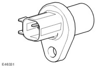
The crankshaft position sensor is located at the lower rear of the engine, next to the transmission. The sensor is connected to a common wire harness using an intermediate harness and a two-pin connector. Both wires go directly to the ECM (the engine control unit). The sensor generates a signal that allows the eSm to (the engine control unit) determine the angular position of the crankshaft and the speed of its rotation. The position of the crankshaft determines the moment of ignition, the moment of fuel injection, etc. If the signal circuit wires are reversed, the ignition timing will increase by 3°because the ECM (the engine control unit) uses the trailing edge of the signal for each tooth to count.
The driver rotor is pressed into the flywheel and has 36 teeth approximately 3°wide, spaced at 10°intervals, with one tooth missing, providing a hard-set set point at 60 degrees BTDC. Due to the orientation of the crankshaft sensor, the target disc uses notches in the surface rather than teeth.
When the magnetic flux changes, which is caused by the passage of the notch past the sensor, a voltage signal is generated in the sensor. The value of the output voltage of the sensor changes with a change in the speed of passage of the notch past the sensor: the higher the speed, the higher the output voltage. It should be noted that the output voltage also depends on the size of the air gap between the sensor and the drive wheel (the larger the gap, the weaker the signal). ECM block (the engine control unit) transmits the crankshaft speed signal to other electronic modules via the CAA bus (controller LAN).
Camshaft position sensor (CMP)
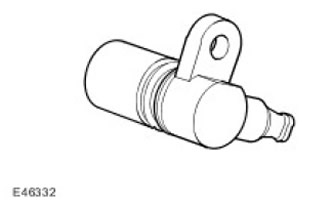
At the rear of the engine, in the cylinder head above the rear cylinders, there are 2 sensors (one per row). Each sensor is a variable reluctance sensor (VRS) and generates 4 pulses for every 2 revolutions of the engine crankshaft. The sensing element is located within a range of 2 mm from the camshaft gear.
The variable cam intake is set to retard and can be moved forward by up to 48 degrees.
The camshaft gear is sintered from metal powder. The four teeth of the wheel allow the EMS to identify the cylinders. The sensor signal is used for:
- Intake camshaft timing
- Cylinder recognition
- Implementation of phased fuel injection
- knock control
- Cylinder identification in diagnostics
- Ignition timing control moves to base data array (data cards), without cylinder correction
- The knock suppression system is disabled (the transition to the use of a safe ignition map with a loss of engine energy indicators is in progress)
- There is no quick alignment of the relative position of the crankshaft and camshafts when starting the engine
- Changing the valve timing is prohibited
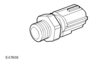
Coolant temperature sensor (ECT)
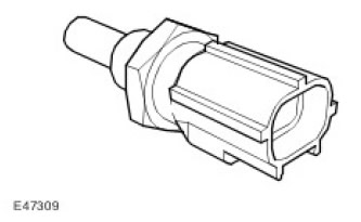
The sensor is located in front of the engine, in the cooling system pipe under the throttle pipe. The ECT temperature sensor is a thermistor and is used to monitor the engine coolant temperature. The coolant temperature sensor is of great importance in engine management. A richer mixture is required to start a cold engine and run smoothly when warmed up, but after warming up the mixture must be leaner to maintain engine performance and low emissions.
The sensor operates in the temperature range from -30 to +125 degrees Celsius. When a malfunction of the coolant temperature sensor is detected, the ECM (the engine control unit) uses the value of the oil temperature sensor.
Oil temperature sensor
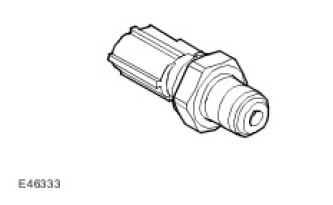
The temperature of the engine oil is monitored by a sensor installed in the lubrication system. The sensor belongs to the type of sensors with NTC (negative temperature coefficient). The oil temperature sensor is located next to the oil pressure sensor, at the front of the engine, on the oil filter bracket.
Rail fuel temperature sensor
The sensor measures the temperature of the fuel in the fuel rail. The sensor signal is used to make a correction to the calculated value of the cyclic feed. The sensor operates in the temperature range from -40 to +150 degrees Celsius. The sensor is installed at the rear of the fuel rail of the right bank of cylinders (row A).
Combined mass air flow/intake air temperature sensor (MAF/IAT)
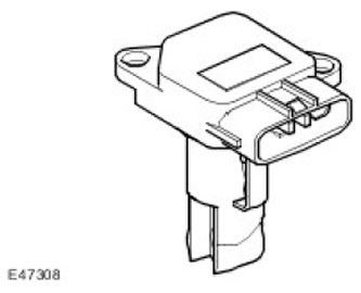
The air mass meter is located in the intake pipe, just behind the air filter housing.
The mass air flow is determined by the intensity of cooling by the incoming air of the heated film sensitive element located in the sensor. The higher the air flow, the more intensively the sensing element is cooled and the lower its electrical resistance. ECM (the engine control unit) uses the mass air flow sensor signal to calculate the mass of air entering the engine.
The measured value of the air mass makes it possible to determine the amount of fuel injected to maintain
the stoichiometric composition of the working mixture, which is necessary for the correct operation of the engine and catalytic converters.
In the event of a sensor failure, backup software is provided.
Sensor failure is accompanied by the following symptoms:
- «RPM dip» when making a trip.
- Difficulty starting the engine or stopping the engine after starting.
- Poor engine response/performance.
- The regulation of the composition of the mixture and idle speed is stopped.
- Exceeding the norm of EG toxicity.
- AFM Signal Offset
If the ECM sensor is damaged (the engine control unit) keeps the air temperature at the default value of 25°C.
Manifold absolute pressure sensor (MAP)
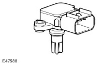
MAP sensor ( (manifold absolute pressure)) generates a voltage proportional to the absolute pressure in the intake manifold. This signal is used by the ECM (the engine control unit) when calculating the engine load. The sensor is located at the rear of the intake manifold.
| contact no | Purpose |
| 1 | MAP signal ( (manifold absolute pressure)) |
| 2 | MAP Sensor Power |
| 3 | Not used |
| 4 | Sensor weight |
MAP sensor output ( (manifold absolute pressure)) together with CKP sensor signals (crankshaft position) and IAT (intake air temperature) used by the ECM (the engine control unit) to calculate the amount of air entering the cylinders. This allows the ECM (the engine control unit) determine the timing of ignition and the duration of fuel injection.
To the MAP sensor ( (manifold absolute pressure)) supply voltage 5 V is supplied from terminal 48 of connector C0634 of the ECM (the engine control unit). The sensor outputs an analog signal on pin 69 of connector C0634 of the ECM (the engine control unit) , which corresponds to manifold absolute pressure and allows the ECM to (the engine control unit) calculate engine load. Track 11 connector C0634 ECM (the engine control unit) is the ECM sensor ground (the engine control unit).
If the MAP signal ( (manifold absolute pressure)) missing, ECM (the engine control unit) uses the default manifold pressure instead, corresponding to engine speed and throttle angle. The engine will continue to operate with somewhat reduced energy performance and increased emissions, although this may not be noticeable to the driver for some time. ECM (the engine control unit) will store fault codes that can be read using T4.
Comments on this article