Location of components of the electronic engine management system
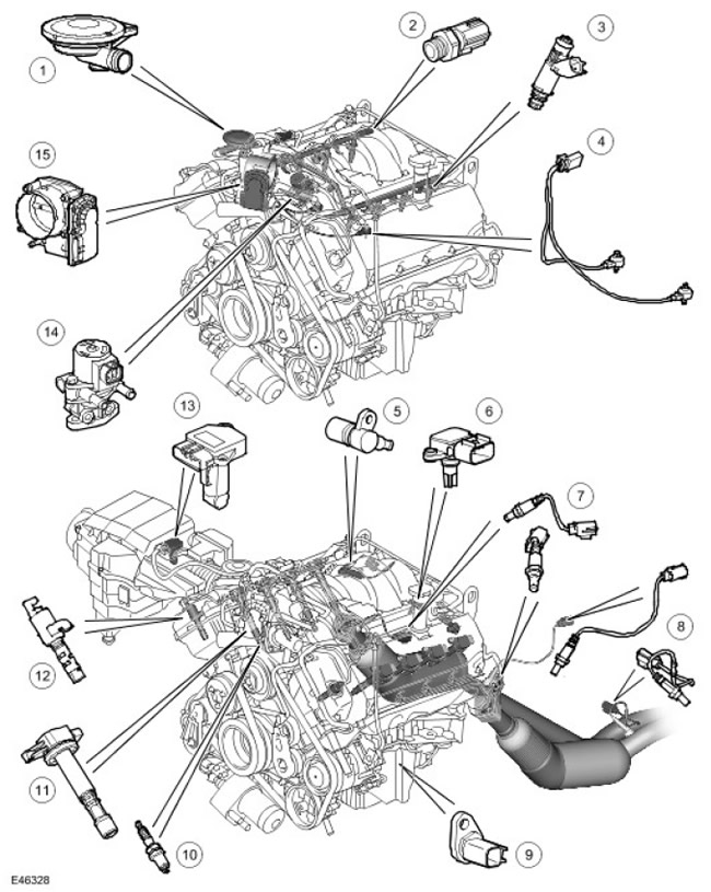
| Item name | Spare part catalog number | Description |
| 1 | - | PCV (forced crankcase ventilation system), |
| 2 | - | Fuel Rail Temperature Sensor |
| 3 | - | Injectors |
| 4 | - | Knock sensor |
| 5 | - | CMP sensor (crankshaft position) |
| 6 | - | MAP sensor ((manifold absolute pressure)) |
| 7 | - | Universal Heated Exhaust Gas Oxygen Sensors (UHEGO) |
| 8 | - | Heated Exhaust Gas Oxygen Sensors (HEGO) |
| 9 | - | CKP sensor (crankshaft position) |
| 10 | - | Spark plugs |
| 11 | - | Ignition coils |
| 12 | - | Variable Valve Timing (VVT) Clutch Control Solenoid Valve |
| 13 | - | MAF sensor (mass air flow) |
| 14 | - | EGR valve (exhaust gas recirculation) |
| 15 | - | Electronic throttle |

| Item name | Spare part catalog number | Description |
| 1 | - | Power relay |
| 2 | - | Transfer case controller |
| 3 | - | ECM (engine control unit) |
| 4 | - | APP (accelerator pedal position sensor), |
| 5 | - | Brake light switch |
| 6 | - | ABS control unit (anti-lock braking system) |
Electronic control system input signal diagram
NOTE: A = Wired

| Item name | Spare part catalog number | Description |
| 1 | - | Power relay |
| 2 | - | CMP sensor (crankshaft position) |
| 3 | - | CKP sensor (crankshaft position) |
| 4 | - | ECT sensor (coolant temperature) |
| 5 | - | APP sensor (accelerator pedal position sensor) |
| 6 | - | MAP ((manifold absolute pressure)) |
| 7 | - | Engine oil temperature sensor |
| 8 | - | MAF sensor (mass air flow) /IAT (intake air temperature) |
| 9 | - | Fuel Rail Temperature Sensor |
| 10 | - | RCM (airbag and seat belt control unit) |
| 11 | - | Brake light switch |
| 12 | - | Clutch Pedal Position Sensor (not used) |
| 13 | - | Knock sensors |
| 14 | - | ECM (engine control unit) |
| 15 | Fuse 60 P | |
| 16 | - | Fuse 25 P |
| 17 | - | Ignition switch |
| 18 | - | Fuse link 11 E |
[Original version of the article on the website: www.LRman.ru]
NOTE: A = Wired; D = CANCAN bus (local area network of controllers)
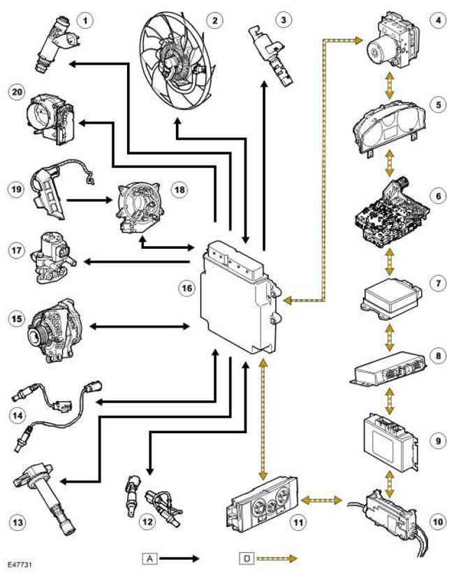
| Item name | Spare part catalog number | Description |
| 1 | - | Injectors |
| 2 | - | Engine cooling system fan. |
| 3 | - | Variable Valve Timing (VVT) Clutch Control Solenoid Valves |
| 4 | - | ABS control unit (anti-lock braking system) |
| 5 | - | Instrument panel |
| 6 | - | TCM (transmission control unit), |
| 7 | - | RCM (airbag and seat belt control unit) |
| 8 | - | Differential controller |
| 9 | - | Transfer case controller |
| 10 | - | Parking brake controller |
| 11 | - | ATC control unit (automatic temperature control) |
| 12 | - | UHEGO (universal heated oxygen sensor) |
| 13 | - | Ignition coils |
| 14 | - | HEGO (Heated oxygen sensor) |
| 15 | - | Generator |
| 16 | - | ECM (engine control unit) |
| 17 | - | EGR valve (exhaust gas recirculation) |
| 18 | - | Spiral spring |
| 19 | - | Cruise control switches |
| 20 | - | Electronic throttle |
General Provisions
The 4.4-liter V8 engine is controlled by an ECM. (engine control unit) manufactured by DENSO. The Engine Management System (EMS) controls the following:
- Fuel supply to the engine.
- Distribution of ignition timing.
- Fueling in a closed loop.
- Detonation control.
- Idle speed adjustment
- Reducing exhaust toxicity.
- OBD (on-board self-diagnostic system),
- Providing an interface with the anti-theft system
- Cruise control
ECM Block (engine control unit) controls the phased supply of fuel to all engine cylinders. The engine uses an ignition system with separate ignition coils (8 coils), which are installed directly on the spark plugs. In order to maintain optimal engine operating conditions, the ECM (engine control unit) detects detonation in each individual cylinder and suppresses it by adjusting the ignition timing on each cylinder.
ECM Management Strategy (engine control unit) is based on the amount of torque requested by the driver. EMS uses various sensors to determine the torque that should be produced by the engine. In addition, EMS uses the CAN bus (local area network controller) to communicate with other electronic units in order to obtain additional information (for example, vehicle speed from the ABS controller (anti-lock braking system)). The EMS processes these signals and decides on the amount of torque to be generated. The required torque is achieved by controlling various actuators that provide air, fuel and ignition timing. (throttle valve, injectors, ignition coils, etc.).
Comments on this article