Contents: Dismantling ⇩ Installation ⇩
Dismantling
1. Disconnect the negative battery terminal.
2. Secure the hood in a vertical position.
3. Drain the coolant from the engine.
COOLING SYSTEM: MOD. K, KV6 engine, ADJUSTMENTS, Draining coolant, flushing and filling the system.
4. Remove the engine soundproofing cover.
ENGINE KV6 - MODIFICATION K, Camshafts of the left cylinder head, Soundproofing engine casing.
5. Remove the battery tray.
ENGINE STARTING AND BATTERY CHARGING SYSTEM, REPAIR WORK, Support tray - battery.
6. Remove the Engine Control Module (ECM).
ENGINE MANAGEMENT SYSTEM: SIEMENS, REPAIR WORK, Engine Control Module (ECM): North American Market Countries.
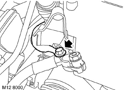
7. Loosen the bolt securing the windshield heater harness to the positive battery bus.
8. Unscrew the 2 bolts securing the wiring harness clamp bar and remove the bar.
9. Disconnect the connector from the junction box and disconnect the engine harness from the interior wiring harness.
10. Move the engine harness to the side.
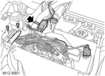
11. Disconnect the connector from the temperature sensor in the junction box.
12. Disconnect the connector from the automatic transmission control unit.
13. Disconnect the cooling system fan harness connector from the junction box.
14. Remove the interior harness mount from the mounting box.
15. Move the interior harness to the side.
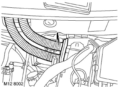
16. Remove the air duct from the mounting box.
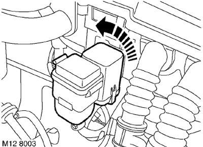
17. Turn the windshield heater relay counterclockwise and remove the relay from the bracket in the junction box.
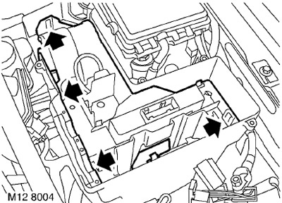
18. Disconnect the 4 latches and remove the platform from the mounting box.
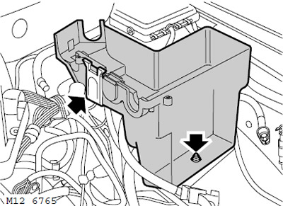
19. Unscrew the nut, release the retainer and remove the mounting box.
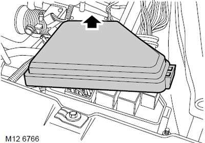
20. Remove the fuse box cover in the engine compartment.
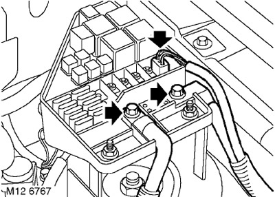
21. Unscrew the 2 bolts securing the battery and starter buses to the fuse box.
22. Disconnect the connector from the fuse box.
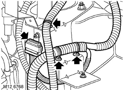
23. Disconnect the ground harness connector.
24. Disconnect the 3 clamps securing the engine harness to the mounting box bracket and place the harness on top of the engine.
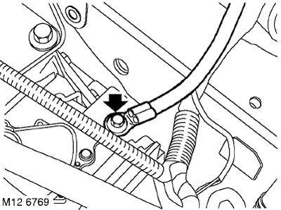
25. Unscrew the bolt securing the engine ground bus.
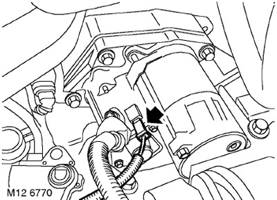
26. Disconnect the connector from the starter solenoid relay.
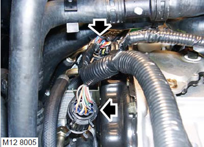
27. Unclip the two transmission wiring harness connectors and disconnect them.
28. Place a rag near the fuel supply hose to prevent spilled fuel from spreading.
CAUTION: Fuel leakage is inevitable during this operation. Take safety measures to prevent fire or explosion.
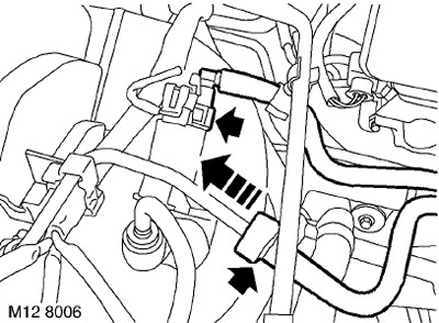
29. Slide back the rubber bushing on the fuel line connector, release the connector and disconnect the supply line from the fuel rail.
CAUTION: Always plug the fittings and holes to protect the system from dirt.
30. Release the purge hose from the supporting clamps.
31. Loosen the clamp and disconnect the hose from the canister purge valve.
CAUTION: Always plug the fittings and holes to protect the system from dirt.
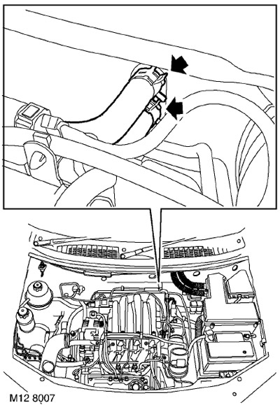
32. Loosen the clamps and disconnect the inlet and outlet hoses from the heater radiator.
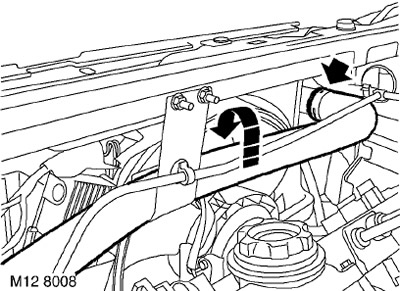
33. Release the upper radiator hose from the bracket, loosen the clamp and remove the upper hose from the radiator.
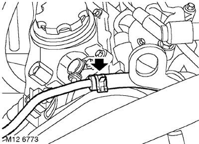
34. Loosen the clamp and disconnect the expansion tank hose from the intake manifold.
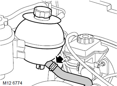
35. Loosen the clamp and disconnect the hose from the bottom of the expansion tank.
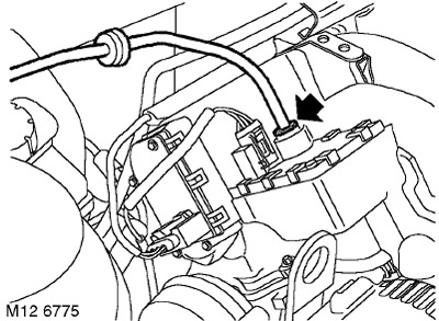
36. Press the connector shoulders and disconnect the brake booster hose from the intake manifold receiver.
CAUTION: Always plug the fittings and holes to protect the system from dirt.
37. Raise the car on a lift.
38. Remove the front wheels.
39. Remove the cotter pin from the hub mounting nut to the drive shaft.
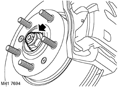
40. With the help of a partner holding the brake pedal depressed, unscrew and dispose of the nuts securing the right and left drive shafts to the hubs.
41. Remove the rear cross member.
FRONT SUSPENSION, REPAIR WORK, Front subframe.
42. Remove the exhaust pipe.
COLLECTORS AND EXHAUST SYSTEM: MOD. K, V6 engine, REPAIR WORK, Downpipe: North American market countries.
43. Raise one rear wheel so that you can rotate the driveshaft to gain access to the bolts.
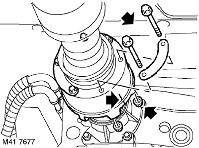
44. To simplify subsequent assembly, mark the position of the viscous coupling in relation to the transfer case flange.
45. Unscrew 6 nuts and remove the bolts securing the propeller shaft to the drive flange of the transfer case.
46. Remove the propeller shaft from the transfer case drive flange and tie it to the side.
CAUTION: When removing the three-roller joint from the transfer case, care must be taken. To avoid damaging the boot, it must not be completely stretched, and the joint housing must be protected from impacts.
47. Drain the oil from the gearbox.
AUTOMATIC TRANSMISSION: JATCO, ADJUSTMENTS, Replacement of working fluid in the box.
48. Drain the oil from the transfer case.
TRANSFER CASE, ADJUSTMENTS, Changing the transmission oil in the transfer case: North American market countries.
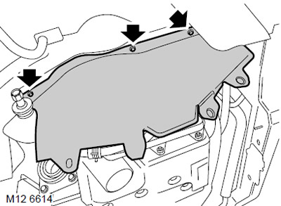
49. Unscrew the 6 bolts securing the right and left mudguard panels and remove the panels.
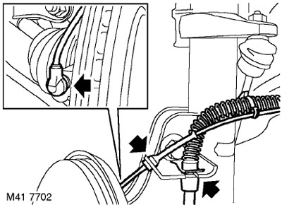
50. Release the brakes from the fastenings to the brackets of the right and left shock absorbers.
51. Release the wheel speed sensor wiring harness from the clamp.
52. Disconnect the yaw rate sensors from the right and left hubs.
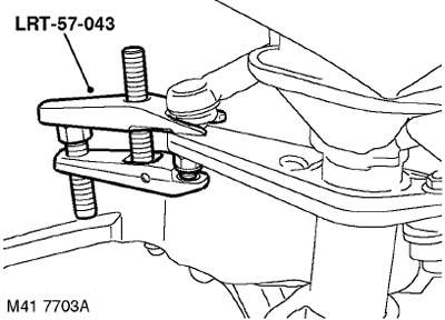
53. Unscrew the nuts securing the right and left ball joints of the tie rod ends to the steering arms.
54. Screw an M12 nut onto each of the ball joints flush with the end of the threaded portion of the joint.
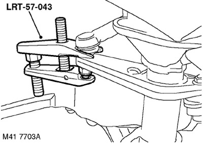
55. Using tool 57-043, separate the ball pins from the right and left steering knuckles. Unscrew the M12 nuts and remove the ball pins from the steering knuckles.
56. Move the right and left hubs outward and release the drive shafts from the hubs.
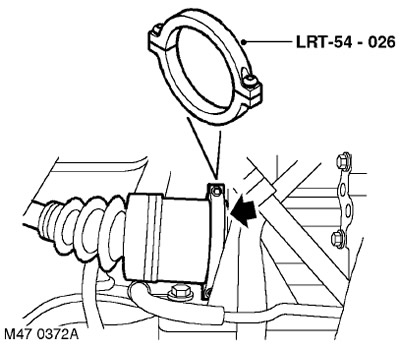
57. Using tool 54-026, remove the drive shafts from the transfer case and from the gearbox.
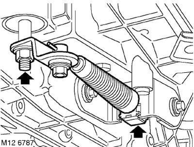
58. Loosen the nut securing the selector lever to the gearbox selector shaft and remove the selector lever from the shaft.
59. Disconnect the selector cable mount from the gearbox bracket, remove the cable and secure it to the side
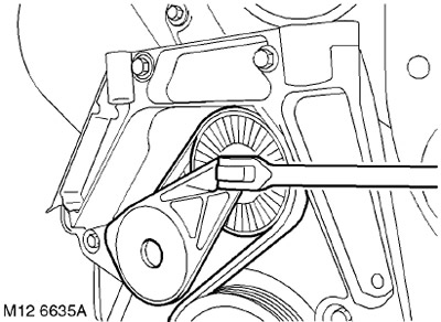
60. Using a 3/8" ratchet, release the belt tensioner and remove the belt from the A/C compressor pulley.
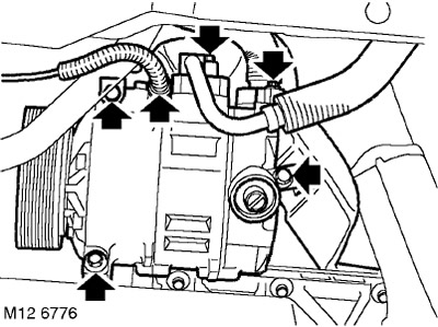
61. Disconnect the connector from the cooling system compressor.
62. Mark the position of the heat shield on the air conditioning compressor, unscrew the 3 bolts securing the compressor to the front plate and to the cylinder block. Remove the cooling system compressor with the heat shield and set them aside.
63. Lower the car on the lift.
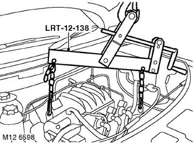
64. Attach the LRT-12-138 adjustable crosshead hoist to the engine.
65. Raise the hoist to relieve the load on the engine mounts.
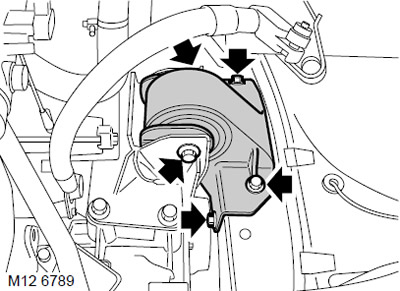
66. Remove the through bolt securing the left engine support to the gearbox.
67. Unscrew the 4 screws securing the left support to the body and remove the support.
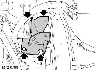
68. Unscrew the 4 bolts securing the left support bracket to the gearbox and remove the bracket.
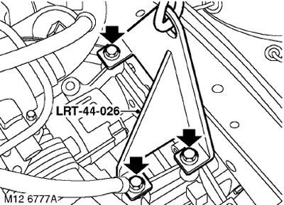
69. Attach the LRT-44-026 lifting eyes to the gearbox using the gearbox bracket mounting bolts.
70. Place a wooden block on the jack, place the jack with the block under the gearbox and raise the jack enough to support the weight of the gearbox. Unhook the chain with the hook from the rear eye on the engine and hook it to the eye on the gearbox.
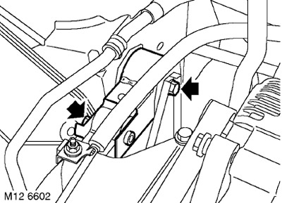
71. Remove the bolt securing the upper right engine crossmember to the upper bracket.
72. Loosen the bolt securing the upper right engine crossmember to the body and move the crossmember away from the upper bracket.
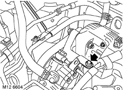
73. Loosen the bolt securing the power steering pump pipe to the front engine plate.
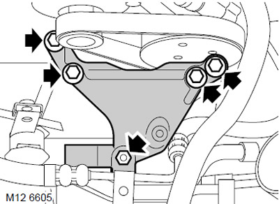
74. Unscrew the nut and 4 bolts securing the upper engine bracket to the right hydraulic support and to the front mount on the engine.
75. Remove the power steering pump pipe bracket from the hydraulic support and move the pipe to the side.
76. Loosen the bolt securing the power steering pump pipe to the front engine plate.
77. Remove the upper bracket.
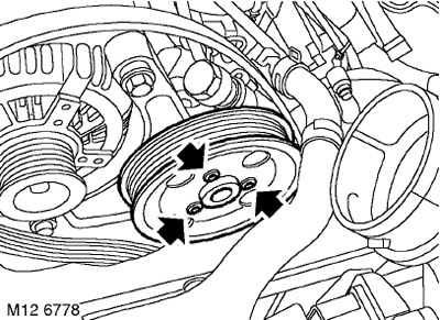
78. Unscrew the 3 bolts securing the power steering pump pulley and remove the pulley.
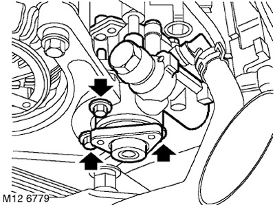
79. Unscrew the 3 bolts securing the power steering pump to the front plate, move the pump away and secure it.
80. With the help of a partner, avoiding obstacles, lower the engine with the gearbox to the floor.
Installation
1. With the help of a partner, lift the engine into the engine compartment.
2. Install the power steering pump on the front plate, screw in the bolts and tighten them to a torque of 25 Nm.
3. Install the pulley on the power steering pump, screw in the bolts and tighten them to a torque of 9 Nm.
4. Install the upper bracket on the engine and on the right hydraulic support, screw in the bolts and tighten them to a torque of 100 Nm.
5. Install the power steering pump hose bracket onto the right hydraulic support, fit the nut and tighten it to 85 Nm.
6. Place a wooden block on the jack, place the jack with the block under the gearbox and raise the jack enough to support the weight of the gearbox. Unhook the chain with the hook from the eye on the gearbox and hook it to the rear eye on the engine.
7. Lower the jack under the gearbox and remove the jack.
8. Unscrew the bolts securing the 44-026 lifting eye to the gearbox and remove the eye.
9. Install the left bracket on the gearbox, screw in the bolts and tighten them to a torque of 85 Nm.
10. Install the left support on the body, screw in the bolts and tighten to a torque of 48 Nm.
11. Position the gearbox bracket against the left support, insert the through bolt and tighten it to 100 Nm.
12. Install the upper right cross member on the bracket, screw in the bolt and tighten it to a torque of 100 Nm.
13. Tighten the upper crossmember mounting bolt to the body to a torque of 100 Nm.
14. Install the power steering pump on the front engine plate, screw in the bolt and tighten it to 25 Nm.
15. Lower the chains, unhook and remove the LRT-12-138 crossbar.
16. Raise the car on a lift.
17. Install the cooling system compressor on the front plate of the engine and on the cylinder block, align the holes in the heat shield, screw in the bolts and tighten them to a torque of 25 Nm.
18. Connect the electrical connector to the air conditioning compressor.
19. Using a 3/8" ratchet, loosen the tensioner and place the belt on the accessory pulleys.
20. Install the cable housing onto the gearbox bracket and secure with the clamp.
21. Install the selector lever on the selector shaft, tighten the nut and tighten it to a torque of 25 Nm.
22. Wipe the splines on the ends of the drive shafts and their seats in the front hubs.
23. Install new retaining rings on the splines of the inner joints of the right and left drive shafts.
24. Insert the drive shafts into the transfer case and into the gearbox, checking that the retaining rings of each shaft fit into their sockets.
25. Insert the right and left drive shafts into the front hubs.
26. Install new drive shaft mounting nuts, but do not tighten them fully at this stage.
27. Clean the conical surfaces of the ball joints and the sockets for their installation from dirt.
28. Connect the right and left tie rod ends to the steering knuckles, fit new nuts and tighten them to a torque of 55 Nm.
29. Wipe the wheel speed sensors and mating surfaces.
30. Apply anti-seize grease to both sensors and install them into the front hubs.
CAUTION: Make sure the sensor is fully inserted into the hub and touches the inductive toothed ring.
31. Install the brake hoses of the right and left wheels on the shock absorber brackets and secure with clamps.
32. Install the left and right mudguard panels, screw in and tighten the mounting bolts.
33. Check that the mating surfaces of the propeller shaft flange and the rear axle drive shaft flange are clean.
34. Install the cardan shaft on the transfer case drive flange so that the previously applied marks are aligned. Tighten the nuts and bolts to a torque of 42 Nm.
35. Install the rear beam in place.
FRONT SUSPENSION, REPAIR WORK, Front subframe.
36. Fill the transfer case with oil to the required level.
TRANSFER CASE, ADJUSTMENTS, Changing the transmission oil in the transfer case: North American market countries.
37. Install the exhaust pipe.
COLLECTORS AND EXHAUST SYSTEM: MOD. K, V6 engine, REPAIR WORK, Downpipe: North American market countries.
38. With the assistant pressing the brake pedal, tighten the front hub nuts to a torque of 400 Nm.
39. Pin the drive shaft mounting nuts.
40. Install the front wheels, tighten the nuts and tighten them to a torque of 115 Nm.
41. Lower the car on the lift.
42. Connect the brake booster hose to the intake manifold.
43. Connect the coolant hose to the bottom of the expansion tank and secure it with a clamp.
44. Connect the expansion tank hose to the intake manifold and secure it with a clamp.
45. Connect the upper hose to the radiator and secure with a clamp. Secure the hose in the clamp.
46. Connect the heater inlet and outlet hoses and secure them with a clamp.
47. Secure the throttle control cable to the throttle sector and the cable casing to the bracket.
48. Connect the hose to the purge solenoid valve of the adsorber.
49. Secure the purge hose in the clamp.
50. Connect the fuel line to the fuel rail, slide the rubber bushing onto the connection.
51. Attach the multi-position connectors to the transmission and secure the connectors to the clips on the support.
[The article was copied from the website: lrman.ru]
52. Connect the connector to the starter solenoid relay.
53. Place the ground wire on the gearbox and tighten the mounting bolt. Tightening torque 25 Nm.
54. Place the engine harness on the mounting box bracket and secure the harness with a clamp.
55. Connect the ground harness connector.
56. Connect the connectors to the fuse box in the engine compartment.
57. Connect the battery and starter buses to the fuse box in the engine compartment, screw in the bolts and tighten them to 8 Nm.
58. Replace the fuse box cover.
59. Install the mounting box, secure it with the clamp, tighten the nut and tighten it to a torque of 9 Nm.
60. Install the platform into the mounting box.
61. Install the air duct onto the mounting box.
62. Install the interior harness into the mounting box, secure the harness bushing and clamp.
63. Connect the cooling system fan harness connector to the junction box.
64. Connect the connector to the temperature sensor of the junction box.
65. Connect the connector to the gearbox control unit.
66. Route the engine harness to the mounting box and secure the grommet.
67. Install the harness clamp and secure it with screws.
68. Connect the engine harness connector to the passenger compartment harness and install the connector into the mounting box.
69. Install the windshield heater harness to the positive battery busbar and tighten the mounting bolt to 15 Nm.
70. Install the engine control module (ECM).
ENGINE MANAGEMENT SYSTEM: SIEMENS, REPAIR WORK, Engine Control Module (ECM): North American Market Countries.
71. Reinstall the battery tray.
ENGINE STARTING AND BATTERY CHARGING SYSTEM, REPAIR WORK, Support tray - battery.
72. Fill the cooling system with coolant.
COOLING SYSTEM: MOD. K, KV6 engine, ADJUSTMENTS, Draining coolant, flushing and filling the system.
73. Connect the negative terminal to the battery.
74. Fill the gearbox with transmission oil.
AUTOMATIC TRANSMISSION: JATCO, ADJUSTMENTS, Replacement of working fluid in the box.
75. Install the engine soundproofing cover.
ENGINE KV6 - MODIFICATION K, Camshafts of the left cylinder head, Soundproofing engine casing.
76. Untie the hood and close it.
Comments on this article