car logo Ford
car logo Volkswagen
car logo BMW
car logo Opel
car logo Audi
car logo Toyota
car logo Peugeot
English Русский
Български
Беларускі
Український
Српски
Hrvatski
Română
Polski
Slovenský
Magyar


Main
Freelander
Discovery
Range Rover
Defender
Contacts
Articles

Front pinion bearing (Freelander 2)

 
  • Main
  • Freelander
  • Freelander 2
  • Chassis
  • Rear drive axle
  • Front pinion bearing
 
        5  
Contents: Removal ⇩ Installation ⇩

Removal


1. Raise and lower the vehicle onto stands.

2. Drain the transmission fluid. Refer to procedure: Draining Transmission Fluid from Differential and Filling Differential with Transmission Fluid (205-02 Rear Drive Axle/Differential, General Procedures).

3. Remove the rear differential. Refer to the procedure: Differential Case (205-02 Rear Drive Axle/Differential, Removal and Installation).

4. Remove the differential housing bolts.
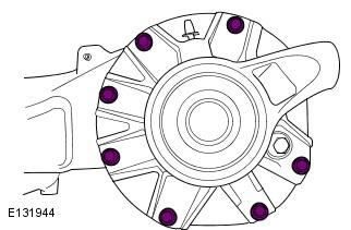
4. Remove the differential housing bolts.


5. Remove the differential housing.
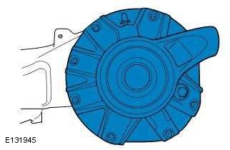
5. Remove the differential housing.


6. Remove and discard the differential housing seal.
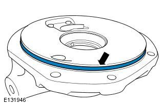
6. Remove and discard the differential housing seal.


7. Remove the ring gear assembly.
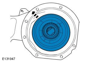


7. Remove the ring gear assembly.


8. Clamp the differential assembly in a suitable vice as shown.
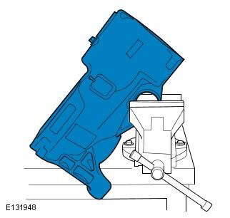
8. Clamp the differential assembly in a suitable vice as shown.


9. Using a special tool, remove the pinion shaft seal.

CAUTION: Make sure that the pinion recess is not damaged when removing the seal.
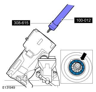

CAUTION: Make sure that the pinion recess is not damaged when removing the seal.


10. Using special tools, remove the pinion shaft nut.

WARNING: Use of high torque.


CAUTION: Do not use air tools or heat to remove the nut (this may contaminate the front bearing). Failure to do so may result in damage to this component.


NOTE: The special tool must be turned clockwise to remove the pinion shaft nut.
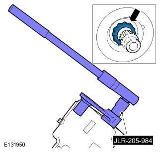

NOTE: The special tool must be turned clockwise to remove the pinion shaft nut.


11. Secure the differential housing in the special tool. Place the support bolt in the lowest position.
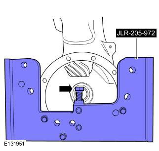
11. Secure the differential housing in the special tool. Place the support bolt in the lowest…


12. Using a suitable press, remove the differential pinion shaft.

CAUTION: Failure to use support plates to secure the fixture to the press may result in twisting or damage to the crankcase.
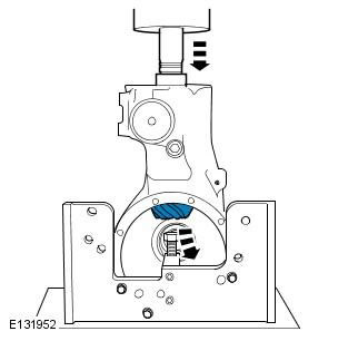

CAUTION: Failure to use support plates to secure the fixture to the press may result in twisting or…


13. Remove and discard the pinion shaft soft lining.
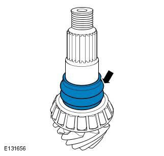


13. Remove and discard the pinion shaft soft lining.


14. Remove the rear bearing inner race.
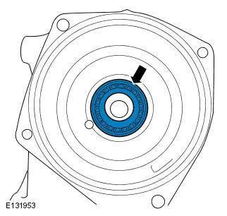
14. Remove the rear bearing inner race.


15. Using special tools, remove the outer ring of the rear bearing of the drive pinion shaft.
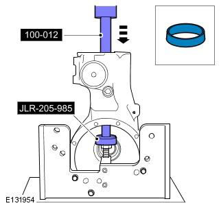
15. Using special tools, remove the outer ring of the rear bearing of the drive pinion shaft.


16.
  • Remove the differential from the support.
  • Clean the pinion shaft thoroughly, paying particular attention to the threads.
  • Using a suitable cleaning fluid, thoroughly clean the differential housings.

CAUTION: Working on the rear differential requires absolute cleanliness. Always cover all open openings with lint-free material to prevent entry of foreign material. Failure to do so may result in component damage.


Installation


1.
  • Secure the differential housing in a special tool.
  • Using a suitable press and special tool, install the outer race of the rear bearing of the pinion shaft.

CAUTION: Do not clean or lubricate the new pinion shaft rear bearing, it is supplied in a light grease. Failure to do so will result in the rear bearing having to be replaced before the differential is assembled.
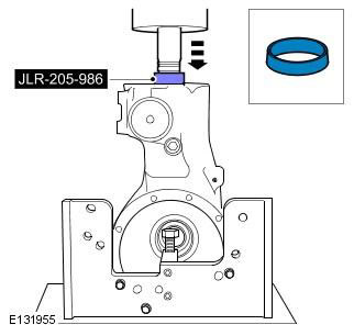

CAUTION: Do not clean or lubricate the new pinion shaft rear bearing, it is supplied in a light…


2. Install a new pinion shaft gasket.
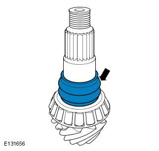
2. Install a new pinion shaft gasket.


3.
  • Install the pinion shaft into the differential housing.
  • Lubricate the support bearing at the pinion gear with differential oil.
  • Place the support bolt in its highest position.
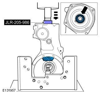
Place the support bolt in its highest position.


4. Using a suitable press and special tool, install the inner race of the rear bearing of the pinion shaft.


CAUTION: Do not clean or lubricate the new pinion shaft rear bearing, it is supplied in a light grease. Failure to do so will result in the rear bearing having to be replaced before the differential is assembled.
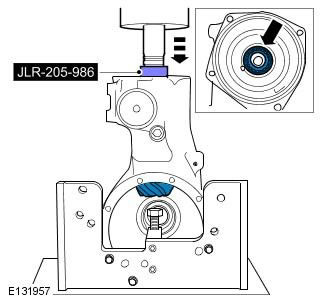

CAUTION: Do not clean or lubricate the new pinion shaft rear bearing, it is supplied in a light…


5. Clamp the differential assembly in a suitable vice as shown. Remove the differential from the support.
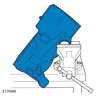
5. Clamp the differential assembly in a suitable vice as shown. Remove the differential from the…


6. Using the special tools, install the new pinion nut. Tighten to the specified torque 250 Nm (184 lbs/ft).

WARNING: Use of high torque.


The special tool should be turned counterclockwise to install the pinion shaft nut.


Do not use an air tool to install the nut. Failure to do so may result in damage to this component.


NOTE: The pinion shaft gasket begins to collapse at minimum torque 250 Nm (184 lbs/ft).
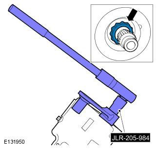


NOTE: The pinion shaft gasket begins to collapse at minimum torque 250 Nm (184 lbs/ft).


7.
  • Using the special tool, check the torque required to rotate the pinion shaft. Recommended torque 1.1+/-0.2 Nm
  • If the specified torque for rotating the pinion shaft is not achieved, use special tools to tighten the flange nut in one degree increments, checking the torque after each increment until the recommended torque is achieved 1.1+/-0.2 Nm

Make sure the specified shaft rotation torque is not exceeded. If excessive preload is applied to the joint, the pinion shaft must be removed and a new shim, pinion shaft rear bearing, pinion shaft rear bearing outer race and pinion nut must be installed.


To obtain a constant value, the special tool should be rotated at a speed of 60 rpm (1 revolution per second).


Before measuring the torque, the pinion shaft should be turned manually two full revolutions.
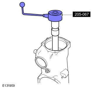

Before measuring the torque, the pinion shaft should be turned manually two full revolutions.


8. Using a suitable press, special tool and adapter, install the pinion bearing seal.


CAUTION: Do not lubricate the pinion oil seal.
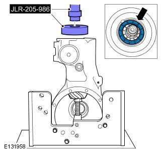

CAUTION: Do not lubricate the pinion oil seal.


9. Install the ring gear assembly.
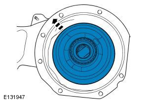
9. Install the ring gear assembly.


10. Install the differential housing seal. Apply a small amount of clean differential oil to the new seal.

Make sure the mating surfaces are clean, failure to do so may result in damage to the differential.


Make sure that the new seal is not twisted during installation, failure to do so may result in damage to the differential.
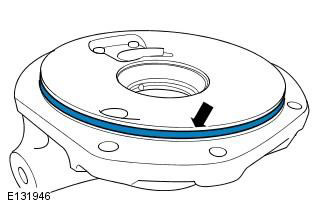

Make sure that the new seal is not twisted during installation, failure to do so may result in…


11. Install the differential housing bolts. Tighten the 7 bolts to 110 mm 29 Nm.
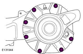
11. Install the differential housing bolts. Tighten the 7 bolts to 110 mm 29 Nm.


12. Install the rear differential. Refer to procedure: Differential Case (205-02 Rear Drive Axle/Differential, Removal and Installation).

13. Fill the differential case with transmission fluid. Refer to procedure: Draining Transmission Fluid from Differential and Filling Differential with Transmission Fluid (205-02 Rear Drive Axle/Differential, General Procedures).


This article is available at russian, bulgarian, belarusian, ukrainian, serbian, croatian, romanian, polish, slovak, hungarian
Article review: Roman Mitrofanov


Previous articles
Rear Axle Specifications
Description and principle of operation
Active clutch
Operating principles of an active clutch
Draining transmission oil from the differential
Activated Clutch Filler
Automatic clutch
Active Clutch Control Unit

Current article
Front pinion bearing

Next articles
Drive gear seal
Rear axle seal


Similar articles from Land Rover repair manuals:
• Wheel bearing and front wheel hub Discovery 3 (2004-2009)
• Front and rear suspension Range Rover 3 (2001-2012)
• Wheel bearing and front wheel hub Defender 2007+ (2007-2016)

Comments on this article

Пётр
09.11.2015
20:20
Спец инструментом может в 12-ти гранная головка на 41 Обрезанная головка была приварена к трубе соответствующего диаметра длиной около 150 мм, с другой стороны приваривается подходящая гайка. Чтобы одновременно затягивать гайку и контролировать сопротивление проворачиванию (преднатяг подшипников), необходимо изготовить еще один ключ, свободно проходящий сквозь первый. Второй ключ предназначен для того, чтобы держать вал за шлицы муфты. Поскольку вал имеет 23 шлица при диаметре 22 мм и ничего подходящего в своем отечестве найти не удалось, пришлось использовать то, что под рукой. А именно переднюю ступицу от 08, шлицевая часть которой была обточена снаружи до 30 мм и разрезана на сегменты по 4 шлица, сегменты вложены в трубу, прижаты хвостовиком к её стенкам и приварены через заранее высверленные отверстия. В итоге получилось два торцевых трубчатых ключа, которыми можно одновременно удерживать хвостовик и затягивать гайку. Надеюсь информация полезна.
answer quote
Dcov
07.01.2016
00:28
Пётр,
Полезна. Спс !
answer quote
Лео
07.01.2018
09:19
07-00033-SX диск сцепления, отсюда подойдет ступица на шлицы вала
answer quote
андей
27.03.2018
23:02
второй ключ не делали, заклинили шестерню тряпкой с обратной стороны
answer quote
Геннадий
01.07.2019
07:31
В качестве ключа для удерживания вала хорошо подходит ступица от ведомого диска сцепления Audi A4
answer quote


How much will 21 + 28 =


Freelander 2 
  • General information
  • Using the manual
  • Repair technique
  • Precautionary measures
  • Road test
  • Fault codes
  • Identification codes
  • Jacking and lifting
  • Maintenance - Diesel
  • Maintenance - petrol
  • Chassis
  • Suspension
  • Front suspension
  • Rear suspension
  • Wheels and tires
  • Terrain response
  • Transmission system
  • Cardan shaft
  • Rear drive axle
  • Rear axle shafts
  • Front axle shafts
  • Brake system
  • Parking brake
  • Hydraulic brake
  • Brake booster
  • Anti-lock braking system
  • Exchange rate stability
  • Steering
  • Steering column
  • Power unit
  • Engine device
  • Engine repair
  • Description of the cooling system
  • Cooling system repair
  • Fuel supply
  • Drive units
  • Launch system
  • Ignition system
  • Exhaust toxicity
  • Air filtration
  • Fuel vapor control
  • Electronic control part
  • Automatic gearbox
  • Gearbox cooling
  • Automatic transmission controls
  • Mechanical transmission
  • Transfer case
  • Exhaust system
  • Fuel tank and lines
  • Speed control
  • Electrical equipment
  • Climate control system
  • Climate control
  • Additional climate control
  • Instrument panel
  • Sound signal
  • Information and messages
  • Assistance with parking
  • Battery and alternator
  • Information and entertainment
  • Outdoor Lighting
  • Interior lighting
  • Communication network
  • Wiring harnesses
  • Anti-theft system
  • Multifunctional modules
  • Body and coating
  • Body front panels
  • Lockable body parts
  • Interior trim
  • Rear view mirrors
  • Car seats
  • Glass, frames and mechanisms
  • Instrument panel and console
  • Handles, locks, latches
  • Windshield wipers and washers
  • Sunroof
  • Bumpers
  • Seat belt system
  • Restraint system
  • Body repairs
  • Front end repairs
  • Roof element repairs
  • Side panel repairs
  • Tailgate repairs
  • Subframe and mounts

Freelander 1 
  • General information
  • Using the manual
  • Precautionary measures
  • Technique
  • Specifications
  • Connection tightening torques
  • Maintenance
  • Power unit
  • Diesel engine Td4
  • Petrol engine K1.8
  • Piston group K1.8
  • KV6 petrol engine
  • Piston group KV6
  • Decreased toxicity
  • Motor control EDC
  • Engine management MEMS
  • Motor control Siemens
  • Fuel supply diesel Td4
  • Fuel supply for K1.8 engine
  • Fuel supply of KV6 engine
  • Cooling diesel Td4
  • Engine cooling K1.8
  • Engine cooling KV6
  • Exhaust system Td4
  • Exhaust system K1.8
  • Exhaust system KV6
  • Clutch
  • Mechanical transmission
  • Transfer case
  • Automatic gearbox
  • Chassis
  • Drive shafts
  • Rear axle and final drive
  • Steering
  • Front suspension
  • Rear suspension
  • Brake system
  • Body and coating
  • Passive safety
  • Doors, locks and glass
  • Exterior body parts
  • Interior trim details
  • Seats
  • Roof hatch
  • Roof
  • Body geometry
  • Body parts repair
  • Sealing and corrosion
  • Electrical equipment
  • Heating and ventilation
  • Air conditioning
  • Windshield wipers and washers
  • Starting engine and charging
  • Lighting and headlights
  • Control modules
  • Safety system
  • Window management
  • Entertainment systems
  • Wiring harnesses
  • Governing bodies
  • Devices


LRman.ru © 2013-2026 | Mobile version | Free Lander | Discovery | Range Rover | Defender | Contacts | | Sitemap |
Car repair and service instructions Land Rover: Freelander, Discovery, Range Rover, Defender
We use cookies to make pages load faster and provide a more user-friendly experience 🍪