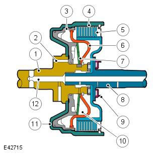
| Pos. | Spare part number | Name |
| 1 | - | Input shaft |
| 2 | - | Main pressure supply channel |
| 3 | - | Piston |
| 4 | - | Cylinder - outer thrust disc |
| 5 | - | Friction disc pack |
| 6 | - | Partition |
| 7 | - | Diaphragm spring |
| 8 | - | Output shaft |
| 9 | - | Bearing |
| 10 | - | Centrifugal pressure component balancing cavity |
| 11 | - | Piston chamber |
| 12 | - | Lubrication channel |
The gearbox uses three drive and two brake clutches (B2 is a multi-disc brake clutch & B1 - double brake band). Each clutch, depending on the output torque, contains one or more friction discs. A typical clutch consists of several steel outer discs and inner discs coated on both sides with friction material.
| Clutch/brake | Operating principle |
| Coupling C1 | Connects the front planetary gear carrier to the rear sun gear of the rear planetary gear |
| Coupling C2 | Connects the intermediate shaft to the rear planetary gear carrier |
| Coupling C3 | Connects the front planetary gear carrier to the middle sun gear of the rear planetary gear |
| Brake B1 | Locks the middle sun gear of the rear planetary gear set |
| Brake B2 | Locks the rear planetary gear carrier |
The clutch discs are held in the separated position mechanically by a diaphragm spring and hydraulically by dynamic pressure. Pressure is supplied through a lubrication channel through which fluid flows to the bearings, etc. The working fluid flows through the output shaft openings into the chamber between the partition and the piston. To prevent unintentional engagement of the clutch under the action of the centrifugal component of pressure, a balancing chamber is provided which, in the absence of a static component of pressure, holds the piston in an equilibrium position.
When the clutch needs to be engaged, the main pressure created by the hydraulic pump is supplied to the chamber in front of the piston. The main pressure overcomes the low fluid pressure in the balance chamber. The piston moves, overcoming the pressure of the diaphragm spring, and compresses the disc pack. When the main pressure drops, the diaphragm spring moves the piston away from the disc pack, and the clutch disengages.
One-way clutch
One-way clutch - typical design:
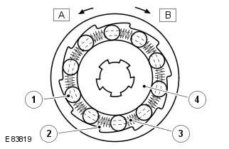
| Pos. | Spare part number | Name |
| 1 | - | Video clip |
| 2 | - | Housing (separator) |
| 3 | - | Spring |
| 4 | - | Inner ring |
The roller clutch of the one-way clutch has 10 parallel rollers located between a smooth cylindrical inner ring and the chamfered surfaces of the clutch body. Springs are used to hold the rollers in place between the two contact surfaces.
When the clutch rotates clockwise, the rollers are caught between the inner race and the chamfered surfaces of the clutch housing, forcing the inner race to rotate, blocking the counterclockwise rotation of the rear planet carrier. When the clutch rotates clockwise, the rollers move away from the chamfered surfaces and are free (without blocking) to rotate with the clutch housing, transmitting motion from the clutch to the rear planet carrier. In this state, the clutch rotates freely on the inner race.
Comments on this article