


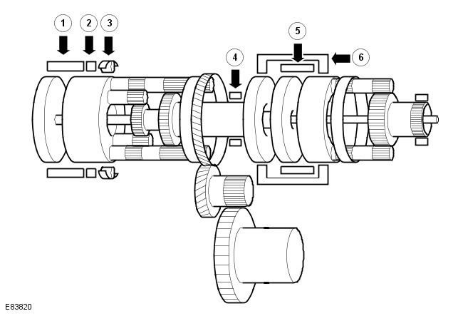
| Pos. | Spare part number | Name |
| 1 | - | Coupling - C2 |
| 2 | - | Brake - B2 |
| 3 | - | One-way clutch - F1 |
| 4 | - | Brake - B1 |
| 5 | - | Coupling - C1 |
| 6 | - | Coupling - C3 |
X = work
Power Flow - 1st Gear, Engine Braking
Operation of electromagnetic valves:
| Gear selector lever position | Solenoid valve | ||||||
| SLC 1 | SLC 2 | SLC 3 | SLB 1 | S1 | S2 | ||
| D | Engine brake | - |
X |
X |
X |
X |
X |
Operation of clutches and brakes:
| Gear selector lever position | Coupling | Brake | One-way clutch | ||||
| C1 | C2 | C3 | B1 | B2 | F1 | ||
| D | Engine brake | X |
- |
- |
- |
X |
X |
When the engine brake is applied, the driving force is transmitted to the gearbox from the wheels via the power transmission unit. The rear planetary carrier is locked against clockwise rotation by the one-way clutch (F1) and the brake (B2). This causes the torque from the wheels to be transmitted directly to the engine, providing engine braking.
Power Flow - 1st Gear
Operation of electromagnetic valves:
| Gear selector lever position | Solenoid valve | ||||||
| SLC 1 | SLC 2 | SLC 3 | SLB 1 | S1 | S2 | ||
| D | 1st gear | - |
X |
X |
X |
- |
- |
Operation of clutches and brakes:
| Gear selector lever position | Coupling | Brake | One-way clutch | ||||
| C1 | C2 | C3 | B1 | B2 | F1 | ||
| D | 1st gear | X |
- |
- |
- |
- |
X |
Planetary gears are in the following states:
- Front planetary gear
- Input: Crown gear
- Blocked: Sun Gear
- Exit: Driver
- Rear planetary gear
- Input: Rear Sun Gear
- Blocked: Driver
- Output: Crown gear
Front planetary gear
The input shaft is driven by a torque converter and rotates clockwise. The planetary gear ring gear rotates clockwise together with the satellite, which also rotates clockwise around its axis and orbit. The planetary gear sun gear is locked by a hydraulic pump, which presses it against the planetary gear ring gear and moves the sun gear in an orbit, rotating around its axis.
The front planetary carrier rotates clockwise in the same direction as the satellite. The clutch (C1) is engaged and locks the planetary carrier in relation to the rear planetary sun gear.
Rear planetary gear
The sun gear of the planetary gear rotates clockwise. The short planet gear rotates counterclockwise. The planet carrier tries to rotate in the same direction, but is held by a one-way clutch (F1).
The long satellite rotates clockwise around its axis, and the middle sun gear rotates counterclockwise idly. The crown gear rotates with the long satellite and drives the reverse pinion, which rotates counterclockwise.
The reverse driven gear is driven counterclockwise and in turn drives the differential ring gear clockwise.
Power Flow - 2nd Gear
Operation of electromagnetic valves:
| Gear selector lever position | Solenoid valve | ||||||
| SLC 1 | SLC 2 | SLC 3 | SLB 1 | S1 | S2 | ||
| D | 2nd gear | - |
X |
X |
- |
- |
- |
Operation of clutches and brakes:
| Gear selector lever position | Coupling | Brake | One-way clutch | ||||
| C1 | C2 | C3 | B1 | B2 | F1 | ||
| D | 2nd gear | X |
- |
- |
X |
- |
- |
Planetary gears are in the following states:
- Front planetary gear
- Input: Crown gear
- Blocked: Sun Gear
- Exit: Driver
- Rear planetary gear
- Input: Rear Sun Gear
- Blocked: Middle Sun Gear
- Output: Crown gear
Front planetary gear
The input shaft is driven by a torque converter and rotates clockwise. The planetary gear ring gear rotates clockwise together with the satellite, which also rotates clockwise around its axis and orbit. The planetary gear sun gear is locked by a hydraulic pump, which presses it against the planetary gear ring gear and moves the sun gear in an orbit, rotating around its axis.
The front planetary carrier rotates clockwise in the same direction as the satellite. The clutch (C1) is engaged and locks the planetary carrier in relation to the rear planetary sun gear.
Rear planetary gear
The planetary gear sun gear and the planet carrier rotate clockwise. The middle sun gear is locked by the brake (B1). The short satellites rotate counterclockwise around their axis and move in a clockwise orbit. The long satellites rotate clockwise around their axis and their orbit.
The crown gear rotates clockwise with the long satellite. The crown gear and reverse pinion rotate clockwise.
The reverse driven gear is driven counterclockwise and in turn drives the differential ring gear clockwise.
NOTE: Engine braking is available when this gear is selected.
Power Flow - 3rd Gear
Operation of electromagnetic valves:
| Gear selector lever position | Solenoid valve | ||||||
| SLC 1 | SLC 2 | SLC 3 | SLB 1 | S1 | S2 | ||
| D | 3rd gear | - |
X |
- |
X |
- |
- |
Operation of clutches and brakes:
| Gear selector lever position | Coupling | Brake | One-way clutch | ||||
| C1 | C2 | C3 | B1 | B2 | F1 | ||
| D | 3rd gear | X |
- |
- |
X |
- |
- |
Planetary gears are in the following states:
- Front planetary gear
- Input: Crown gear
- Blocked: Sun Gear
- Exit: Driver
- Rear planetary gear
- Input: Middle Sun Gear
- Blocked: -
- Output: Crown gear
Front planetary gear
The input shaft is driven by a torque converter and rotates clockwise. The planetary gear ring gear rotates clockwise together with the satellite, which also rotates clockwise around its axis and orbit. The planetary gear sun gear is locked by a hydraulic pump, which presses it against the planetary gear ring gear and moves the sun gear in an orbit, rotating around its axis.
The front planetary carrier rotates clockwise in the same direction as the planetary gear. Clutch (C1) is engaged and locks the planetary carrier in relation to the rear planetary gear sun gear. Clutch (C3) is also engaged and locks the carrier in relation to the middle sun gear.
Rear planetary gear
The short planet and the long planet mesh, causing both planets to lock due to the different directions of rotation. Torque from the sun gear and the middle sun gear is transmitted to the ring gear, which rotates clockwise in the same direction as the planet carrier.
The reverse pinion gear rotates clockwise with the ring gear.
The reverse driven gear rotates counterclockwise and in turn drives the differential ring gear clockwise.
NOTE: Engine braking is available when this gear is selected.
Power Flow - 4th Gear
Operation of electromagnetic valves:
| Gear selector lever position | Solenoid valve | ||||||
| SLC 1 | SLC 2 | SLC 3 | SLB 1 | S1 | S2 | ||
| D | 4th gear | - |
- |
X |
X |
- |
- |
Operation of clutches and brakes:
| Gear selector lever position | Coupling | Brake | One-way clutch | ||||
| C1 | C2 | C3 | B1 | B2 | F1 | ||
| D | 4th gear | X |
X |
- |
- |
- |
- |
Planetary gears are in the following states:
- Front planetary gear
- Input: Crown gear
- Blocked: Sun Gear
- Exit: Driver
- Rear planetary gear
- Input: Rear sun gear, planet carrier
- Blocked: -
- Output: Crown gear
Front planetary gear
The input shaft is driven by a torque converter and rotates clockwise. The planetary gear ring gear rotates clockwise together with the satellite, which also rotates clockwise around its axis and orbit. The planetary gear sun gear is locked by a hydraulic pump, which presses it against the planetary gear ring gear and moves the sun gear in an orbit, rotating around its axis.
The front planetary carrier rotates clockwise in the same direction as the satellite. Clutch (C1) is engaged and locks the planetary carrier in relation to the rear planetary sun gear. The intermediate shaft rotates in the same direction as the input shaft. Clutch (C2) is also engaged and rotates in the same direction as the intermediate shaft.
Rear planetary gear
The planet carrier rotates clockwise with the intermediate shaft. The short satellite rotates clockwise around its axis and moves in an orbit at a higher speed than the sun gear. The long satellite rotates counterclockwise around its axis and orbit. The crown gear rotates clockwise more slowly than the carrier because the carrier impedes the rotation of the long satellite.
The reverse pinion gear rotates clockwise with the ring gear.
The reverse driven gear rotates counterclockwise and in turn drives the differential ring gear clockwise.
NOTE: Engine braking is available when this gear is selected.
Power Flow - 5th Gear
Operation of electromagnetic valves:
| Gear selector lever position | Solenoid valve | ||||||
| SLC 1 | SLC 2 | SLC 3 | SLB 1 | S1 | S2 | ||
| D | 5th gear | X |
- |
- |
X |
- |
- |
Operation of clutches and brakes:
| Gear selector lever position | Coupling | Brake | One-way clutch | ||||
| C1 | C2 | C3 | B1 | B2 | F1 | ||
| D | 5th gear | - |
X |
X |
- |
- |
- |
Planetary gears are in the following states:
- Front planetary gear
- Input: Crown gear
- Blocked: Sun Gear
- Exit: Driver
- Rear planetary gear
- Input: Middle Sun Gear
- Blocked: -
- Output: Crown gear
Front planetary gear
The input shaft is driven by a torque converter and rotates clockwise. The planetary gear ring gear rotates clockwise together with the satellite, which also rotates clockwise around its axis and orbit. The planetary gear sun gear is locked by a hydraulic pump, which presses it against the planetary gear ring gear and moves the sun gear in an orbit, rotating around its axis.
The front planetary carrier rotates clockwise in the same direction as the planetary gear. Clutch (C3) is engaged and locks the planetary carrier in relation to the middle sun gear of the rear planetary gear. The intermediate shaft rotates in the same direction as the input shaft. Clutch (C2) is also engaged and rotates in the same direction as the intermediate shaft.
Rear planetary gear
The middle sun gear rotates clockwise in the same direction as the clutch (C3). Braking the front planetary gear slows the input shaft. The intermediate shaft rotates clockwise in the same direction as the input shaft. The planet carrier also rotates clockwise in the same direction as the intermediate shaft.
The long satellite rotates clockwise around its axis and orbit. The planet carrier rotates faster than the middle sun gear, which balances the middle satellite with the difference in speed. The middle satellite moves in an orbit and rotates around its axis clockwise.
The planetary gear ring gear rotates clockwise. The ring gear rotates faster than the planet carrier because the rotation of the long planet gear is combined with the speed of the carrier. The reverse pinion gear rotates clockwise with the ring gear.
The reverse driven gear rotates counterclockwise and in turn drives the differential ring gear clockwise.
NOTE: Engine braking is available when this gear is selected.
Power Flow - 6th Gear
Operation of electromagnetic valves:
| Gear selector lever position | Solenoid valve | ||||||
| SLC 1 | SLC 2 | SLC 3 | SLB 1 | S1 | S2 | ||
| D | 6th gear | X |
- |
X |
- |
- |
- |
Operation of clutches and brakes:
| Gear selector lever position | Coupling | Brake | One-way clutch | ||||
| C1 | C2 | C3 | B1 | B2 | F1 | ||
| D | 6th gear | - |
X |
- |
X |
- |
- |
Planetary gears are in the following states:
- Front planetary gear
- Entrance: -
- Blocked: -
- Exit: -
- Rear planetary gear
- Entrance: Driver
- Blocked: Middle Sun Gear
- Output: Crown gear
Front planetary gear
The input shaft is driven by the torque converter and rotates clockwise. The intermediate shaft rotates clockwise in the same direction as the torque converter. The clutch (C2) locks the intermediate shaft in relation to the rear planetary carrier.
Rear planetary gear
The planet carrier rotates clockwise in the same direction as the intermediate shaft. The long satellite rotates clockwise around its axis and orbit. The speed of the middle sun gear increases with the speed of the input shaft because it is locked.
The planetary gear ring gear rotates clockwise. The ring gear rotates faster than the planet carrier because the rotation of the long planet gear is combined with the speed of the carrier. The reverse pinion gear rotates clockwise with the ring gear.
The reverse driven gear rotates counterclockwise and in turn drives the differential ring gear clockwise.
NOTE: Engine braking is available when this gear is selected.
Power Flow - Reverse Gear
Operation of electromagnetic valves:
| Gear selector lever position | Solenoid valve | ||||||
| SLC 1 | SLC 2 | SLC 3 | SLB 1 | S1 | S2 | ||
| R | Reverse gear - less than 11V | X |
X |
- |
X |
- |
- |
| R | Reverse gear - more than 11 V | X |
X |
X |
X |
- |
- |
Operation of clutches and brakes:
| Gear selector lever position | Coupling | Brake | One-way clutch | ||||
| C1 | C2 | C3 | B1 | B2 | F1 | ||
| R | Reverse gear - less than 11V | - |
X |
- |
X |
- |
- |
| R | Reverse gear - more than 11 V | - |
- |
- |
- |
X |
- |
Planetary gears are in the following states:
- Front planetary gear
- Input: Crown gear
- Blocked: Sun Gear
- Exit: Driver
- Rear planetary gear
- Input: Middle Sun Gear
- Blocked: Driver
- Output: Crown gear
Front planetary gear
The input shaft is driven by the torque converter and rotates clockwise. The planetary gear ring gear rotates clockwise with the input shaft.
The satellite rotates clockwise around its axis and orbit. The sun gear of the planetary gear is locked by a hydraulic pump, which presses it against the ring gear of the planetary gear and moves the sun gear in orbit, rotating around its axis. The planet carrier rotates clockwise together with the satellite, moving in orbit.
Clutch (C3) is engaged and rotates clockwise and locks the planetary carrier in relation to the middle sun gear of the rear planetary gear.
Rear planetary gear
The middle sun gear rotates clockwise with the clutch (C3), but at a slower speed than the input shaft. The brake (B2) is activated and locks the planet carrier. The long planet rotates counterclockwise and, in turn, rotates the ring gear counterclockwise.
The reverse pinion gear rotates counterclockwise with the ring gear at the same speed.
The reverse driven gear rotates clockwise and in turn drives the differential ring gear counterclockwise.
NOTE: Engine braking is available when this gear is selected.
Power flow in neutral gear
Operation of electromagnetic valves:
| Gear selector lever position | Solenoid valve | ||||||
| SLC 1 | SLC 2 | SLC 3 | SLB 1 | S1 | S2 | ||
| N | Neutral gear | X |
X |
X |
X |
- |
- |
Operation of clutches and brakes:
| Gear selector lever position | Coupling | Brake | One-way clutch | ||||
| C1 | C2 | C3 | B1 | B2 | F1 | ||
| N | Neutral gear | - |
- |
- |
- |
- |
- |
In neutral, power is supplied to all solenoids except the 3-way solenoids; all clutches and brakes are disengaged. This allows the input shaft to rotate the front planetary gear without transmitting torque to the differential ring gear.
Comments on this article