car logo Ford
car logo Volkswagen
car logo BMW
car logo Opel
car logo Audi
car logo Toyota
car logo Peugeot
English Русский
Български
Беларускі
Український
Српски
Hrvatski
Română
Polski
Slovenský
Magyar


Main
Freelander
Discovery
Range Rover
Defender
Contacts
Articles

Braking system with ABS (Discovery 1)

 
  • Main
  • Discovery
  • Discovery 1
  • Chassis
  • Brake system
  • Braking system with ABS
 
        0  
Contents: Description of components ⇩ Brake pipe routing ⇩ Brake pipe routing ⇩

Description of components


Attention:
  • ABS cannot change the physical laws of vehicle motion.
  • ABS cannot prevent loss of vehicle control when cornering at excessive speeds or when the wheels begin to hydroplane.
  • Installing ABS does not guarantee shorter braking distances in all driving conditions.

Brake pipe routing


Note: Left-hand drive models shown. On right-hand drive models, the installation location of the power steering and brake master cylinder is changed.


1. The modulator is installed in the system between the main and working brake cylinders. Physical installation location on the left wing. The modulator has 8 electromagnetic valves (two for each wheel) and a high pressure pump. The unit is not serviced or repaired.

2. The brake force redistribution valve is installed on the left wing.
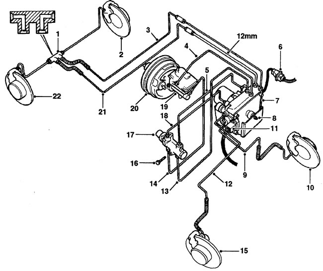
Models with ABS. 1 - double elbow, 2 - left rear brake, 3 - from modulator to left rear brake, 4 -…

Models with ABS. 1 - double elbow, 2 - left rear brake, 3 - from modulator to left rear brake, 4 - from modulator to brake master cylinder, 5 - from modulator to brake force redistribution valve (top), 6 - wiring connector, 7 - modulator, 8 - nut, bushing and support cap, 9 - from modulator to left front brake, 10 - left front brake, 11 - wiring connector, 12 - from modulator to right front brake, 13 - from modulator to brake force redistribution valve (bottom), 14 - from brake master cylinder to brake force redistribution valve (bottom), 15 - right front brake, 16 - bolt, 17 - brake force redistribution valve, 18 - from modulator to brake force redistribution valve (top), 19 - brake master cylinder, 20 - brake booster, 21 - from modulator to right rear brake, 22 - right rear brake.


(The material was taken from the specified website LRman.ru)

Brake pipe routing


Note: Left-hand drive models shown. On right-hand drive models, the installation location of the power steering and brake master cylinder is changed.
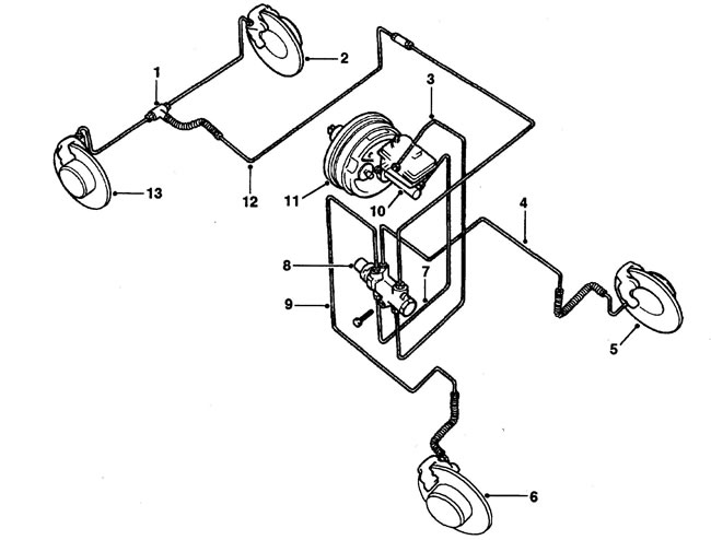

Models without ABS. 1 - tee, 2 - left rear brake, 3 - from the master cylinder to the brakeforce…

Models without ABS. 1 - tee, 2 - left rear brake, 3 - from the master cylinder to the brakeforce redistribution valve (bottom), 4 - from the left front brake to the brakeforce redistribution valve (top), 5 - left front brake, 6 - right front brake, 7 - from the master cylinder to the brakeforce redistribution valve (bottom), 8 - brakeforce redistribution valve, 9 - from the right front brake to the brakeforce redistribution valve (top), 10 - master cylinder, 11 - brake booster, 12 - from the rear brakes to the brakeforce redistribution valve, 13 - right rear brake.
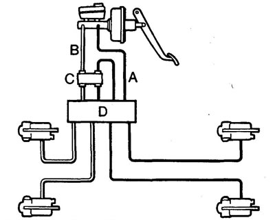

A - first circuit, B - second circuit, C - brake force redistribution valve, D - modulator.

A - first circuit, B - second circuit, C - brake force redistribution valve, D - modulator.


3. The control unit is installed behind the glove compartment on the passenger side. It has a 35-pin connector and is not serviceable. The control unit ensures proper operation of the brakes and can diagnose faults in the electrical components of the system.

4. The sensor gears have 60 teeth. The front brake gear is mounted on the outer diameter of the CV joint, while the rear brake gear is attached to the hub.

5. The diagnostic connector is located behind the dash panel to the left of the steering column for left-hand drive models or to the right of the steering column with five terminals.

6. The malfunction indicator lights up for 1.5-2 seconds after the ignition is turned on. If there are no faults in the system, the indicator goes out for 0.5 seconds and lights up again until the speed reaches 5-7 km/h.


If the indicator remains illuminated, there is a defect in the system, and full braking control will not be possible in ABS mode. ABS troubleshooting is only performed at specialized service stations.


This article is available at russian, bulgarian, belarusian, ukrainian, serbian, croatian, romanian, polish, slovak, hungarian
Article review: Konstantin Nazarov


Previous articles
Brake system — description
Braking system without ABS

Current article
Braking system with ABS

Next articles
Bleeding the brake system
Bleeding the master brake cylinder
Full system upgrade
Master brake cylinder (with ABS)
Brake master cylinder (without ABS)
Vacuum brake booster
Brake pads (rear wheels)
Front brake caliper


Similar articles from Land Rover repair manuals:
• Anti-Lock Braking System (ABS) fault code Freelander 2 (2006-2014)
• Using roller stands to determine braking forces Range Rover 3 (2001-2012)
• Filling and bleeding the power steering system Defender 2007+ (2007-2016)

Comments on this article


No comments yet


How much will 39 + 41 =


Discovery 3 
  • General information
  • Using the manual
  • Precautionary measures
  • Service Information
  • Technique
  • Health protection
  • Road test
  • Identification codes
  • Jacking and lifting
  • Maintenance - diesel
  • Maintenance - petrol
  • Chassis
  • Suspension
  • Front suspension
  • Rear suspension
  • Wheels and tires
  • Dynamic suspension
  • Cardan shaft
  • Rear drive axle
  • Front drive axle
  • Front axle axles
  • Rear axle axles
  • Brake system
  • Parking brake
  • Hydraulic brake
  • Vacuum brake booster
  • Anti-lock braking system
  • Steering
  • Steering column
  • Power unit
  • Petrol engine 4.0L
  • Petrol engine 4.4L
  • Diesel engine 2.7L
  • Engine cooling
  • Fuel supply
  • Drive units
  • Launch system
  • Ignition system
  • Emission reduction
  • Air filtration
  • Fuel vapor control
  • Electronic control part
  • Car gearbox
  • Clutch
  • All-wheel drive systems
  • Transfer case
  • Exhaust system
  • Fuel tank and lines
  • Acceleration control
  • Electrical equipment
  • Climate control
  • Instruments and control lamps
  • Battery and charging system
  • Information system
  • Lighting and headlights
  • Power distribution
  • Electronic Function Group
  • Body and coating
  • Body elements
  • Interior and body trim
  • Mirrors and glasses
  • Seats
  • Instrument panel and console
  • Handles and locks
  • Windshield wipers and washers
  • Sunroof and bumpers
  • Safety system
  • Body repairs
  • Repair of front end elements
  • Repair of back elements
  • Side panel repair
  • Frame and body mount

Discovery 1 
  • General information
  • Technical specifications
  • Introduction to manual
  • Troubleshooting
  • Power unit
  • Diesel engine Tdi
  • Petrol engine V8i (3.9 l)
  • Petrol engine V8i (4.0 l)
  • Petrol engine Mpi
  • Reducing harmful emissions
  • Fuel system Tdi
  • Fuel system MFi
  • Fuel system SFi
  • Fuel system MPi (MEMS)
  • Cruise control
  • Cooling system (Tdi)
  • Cooling system (V8i)
  • Cooling system (MPi)
  • Exhaust system
  • Transmission
  • Clutch
  • Manual gearbox R380
  • Manual gearbox LT 77
  • Transfer case LT230T
  • Automatic gearbox
  • Cardan shaft
  • Rear axle
  • Front axle
  • Chassis
  • Steering system
  • Front suspension
  • Rear suspension
  • Brake system
  • Wheels and tires
  • Body and interior
  • Passive safety
  • Doors, locks and windows
  • Exterior body parts
  • Interior trim details
  • Seats
  • Electrical equipment
  • Heating and ventilation
  • Air conditioning
  • Windscreen wipers
  • Starting and charging system
  • Equipment and devices
  • Lighting and headlights


LRman.ru © 2013-2026 | Mobile version | Free Lander | Discovery | Range Rover | Defender | Contacts | | Sitemap |
Car repair and service instructions Land Rover: Freelander, Discovery, Range Rover, Defender
We use cookies to make pages load faster and provide a more user-friendly experience 🍪