The separator connection diagram is shown in the figure.
Valve D provides for the release of vapors into the atmosphere (i.e. ventilation of the fuel tank) if the pressure in the vapor recovery system increases excessively, for example if the hoses are blocked. Valve E, when the fuel vapor pressure is in the range of 5-7 kPa, supplies vapor to the accumulator. The F shut-off valve prevents liquid fuel vapor from entering the fuel vapor recovery system in the event of a vehicle rollover, thereby reducing the risk of fire. The fuel vapor accumulator is connected to the resonant chamber of the intake system through a valve that opens and closes according to signals from the control unit.
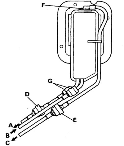
A - vent to atmosphere, B - from fuel tank, C - to fuel vapor accumulator, D and E - pressure relief valves, F - shut-off valve, G - hose connectors.
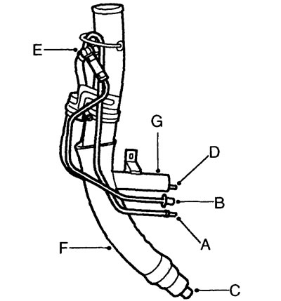
Fuel tank filler neck components: A - to pressure sensor, B - from vapor accumulator to safety valve, C - fuel tank internal ventilation hose, D - to fuel vapor separator, E - overflow safety valve, F - filler neck hose, G - vapor separator.
New scheme
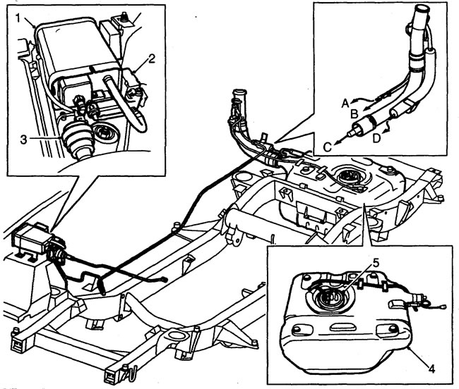
1 - vapor accumulator, 2 - ventilation valve, 3 - shut-off valve, 4 - fuel tank, 5 - fuel pump and fuel level sensor, A - to the pressure sensor, B - from the accumulator to the overflow safety valve, C - internal ventilation of the fuel tank, D - to the vapor separator.
Comments on this article