


Contents: Elements of the hatch panel design ⇩ General Provisions ⇩ Electric sunroof drive ⇩ Sunroof Motor Connector Contacts ⇩ Hatch controller ⇩ Hatch Controller Connector Contacts ⇩ Tightening torque specifications ⇩
Elements of the hatch panel design
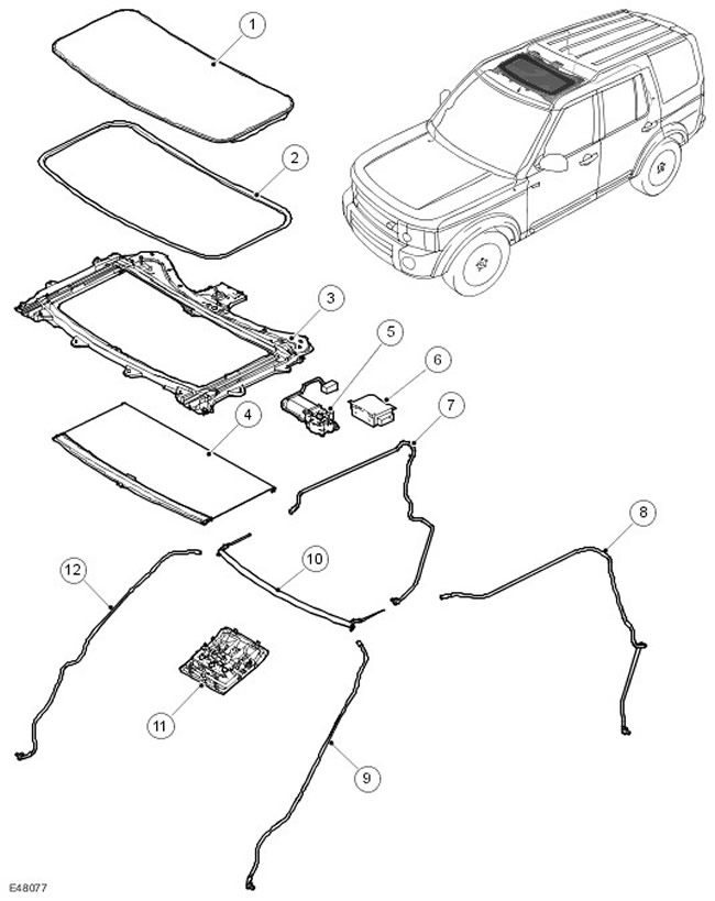
| Item name | Spare part catalog number | Description |
| 1 | - | Glass panel assembly |
| 2 | - | Sealing the glass panel |
| 3 | - | Frame assembly |
| 4 | - | Sun protection blind |
| 5 | - | Electric motor |
| 6 | - | Control module |
| 7 | - | Right rear drainage tube |
| 8 | - | Left rear drainage tube |
| 9 | - | Left front drainage tube |
| 10 | - | Reflector |
| 11 | Access panel | |
| 12 | Right front drainage tube |
General Provisions
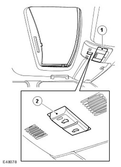
| Item name | Spare part catalog number | Description |
| 1 | - | Access panel |
| 2 | - | Switch |
The sunroof is controlled by a two-position rocker switch located on the sunroof's central console. An electric motor mounted on the sunroof frame moves the sunroof's glass panel into a tilted or open position. The electric motor operates two cables that move the glass panel.
The sunroof frame is bolted to the roof panel at eleven points. The frame is die-cast and holds all sunroof components. Two aluminum guides are attached to either side of the frame. The sunroof motor is mounted to the rear of the frame and secured with three screws.
The sunroof glass panel is attached to the guides at the front and rear points. The tilt and shift positions are achieved by moving the panel attachment points along two fixed trajectories: one end of the panel along the guide, the other together with the fastening.
Electric sunroof drive
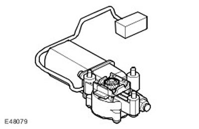
The hatch electric drive includes a worm gear that transmits power to a gear transmission located in a cast casing in the drive reducer. The transmission includes a small pinion that is mounted on the output shaft of the reducer. The pinion is engaged with twisted cables that, together with the pinion, form an analogue of a rack and pinion transmission. The electric motor rotates the pinion, which moves the cables in the required direction.
Sunroof Motor Connector Contacts
| Contact | Position | Input signal/output signal |
| 1 | "Mass" of Hall sensors | - |
| 2 | Power supply for Hall sensors | Input signal |
| 3 | Hall sensor - speed | Output signal |
| 4 | Hall sensor - direction | Output signal |
| 5 | Electric motor A | Input signal |
| 6 | Electric motor B | Input signal |
There are two cables on each side of the pinion. One end of each cable is attached to its guide. The other end of the cable is attached to the pinion by a metal insert on the frame. The cables are routed to the guides in tubes along the frame. When the hatch panel is closed, the cables are inside these tubes behind the frame. The displaced cable is fed into a dual-channel distribution in the frame, which protects the cable, prevents it from jamming and reduces noise. The cables are made of strong spring steel and can therefore move the hatch in both directions along the guides.
The frame rails also have a sunshade. This sunshade is moved manually, regardless of the position of the glass panels. To close the sunshade, pull it forward by the handle until it snaps into place on the frame catch. To close the sunshade, pull it upward by the handle until it releases and leave it in a free position or move it to the fully open position. The sunshade can only be in the fully open or fully closed position.
Drainage hoses are attached to the front and rear corners of the frame. The drainage hoses run inside the front and rear pillars of the body and are designed to drain water that collects in the hatch frame. There are check valves at the ends of the hoses that prevent dirt and moisture from entering them.
Hatch controller
The sunroof controller is located at the rear of the frame and is connected to the electric motor on one side and to the vehicle's electrical system on the other. The controller receives signals from the vehicle's on-board equipment: signals from the LIN bus and switches, and controls the electric motor accordingly. The controller has a trauma safety function.
Hatch Controller Connector Contacts
| Contact | Position | Input signal/output signal |
| 1 | "Mass" of the switch | - |
| 2 | Switch in the "open" position | Input signal |
| 3 | Switch in the "closed" position | Input signal |
| 4 | Not used | - |
| 5 | Not used | - |
| 6 | Emergency case (see note below) | Input signal |
| 7 | "Mass" of the ECU | - |
| 8 | Battery | Input signal |
| 9 | Not used | - |
| 10 | Not used | - |
| 11 | Not used | - |
| 12 | LIN bus | Input signal |
NOTE: Pin 6 is only used in an emergency situation when the vehicle's LIN bus is not working. This pin is not connected to the vehicle's wiring harness or on-board system connector.
NOTE: Connecting pin 6 to ground enables the sunroof controller but with the one-touch control and safety features disabled. Calibration of the sunroof is only required if the battery is disconnected.
NOTE: The sunroof controller will be activated and enabled until pin 6 is disconnected. Under no circumstances should this pin be grounded for an extended period of time.
NOTE: If the electric motor fails, the emergency button in the roof lining for manual sunroof operation will be unavailable.
Tightening torque specifications
| Name | Nm | lb-ft |
| Torx Head Screws for Sunroof Motor | 4 | 3 |
| Sunroof Bolts | 10 | 7 |
| Torx Head Screws for Sunroof Alignment | 6 | 4 |
Comments on this article