Contents: Dismantling ⇩ Installation ⇩
Dismantling
1. Disconnect the negative battery terminal.
2. Remove the accessory drive belt.
ENGINE STARTING AND BATTERY CHARGING SYSTEM, REPAIR WORK, Attachment drive belt - KV6 engine.
3. Remove the right front wheel.
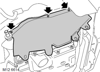
4. Unscrew the 3 bolts securing the right mudguard panel and remove the panel.
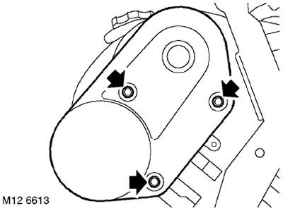
5. Unscrew the 3 bolts securing the rear timing belt cover on the left cylinder head and remove the rear cover.
6. Remove the intake receiver.
COLLECTORS AND EXHAUST SYSTEM: MOD. K, V6 engine, REPAIR WORK, Intake manifold seals: vehicles manufactured before May 2003.
COLLECTORS AND EXHAUST SYSTEM: MOD. K, V6 engine, REPAIR WORK, Intake manifold seals: vehicles manufactured after May 2003.
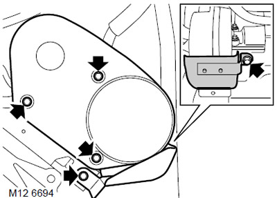
7. Unscrew the 2 bolts securing the heat shield to the rear timing belt cover on the right cylinder head and remove the shield.
8. Unscrew the 3 bolts securing the rear timing belt cover on the right cylinder head and remove the cover.

9. Using a socket head, turn the crankshaft clockwise using the pulley mounting bolt. Align the "SAFE" mark on the crankshaft pulley with the "ARROW" mark on the front engine plate, while the marks on the rear camshaft gears should align as shown.
CAUTION: Do not turn the engine by the camshaft gear mounting bolts or the timing belt.
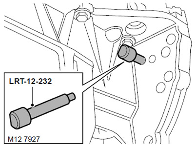
10. Insert the LRT-12-232 pin through the hole in the bottom tray so that the pin enters the hole in the drive disk.
CAUTION: The pin is inserted through the hole in the bottom tray closest to the edge of the tray, as shown in the figure.
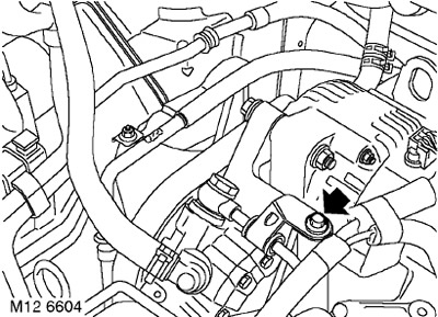
11. Unscrew the bolt securing the power steering pump pipe to the front engine plate.
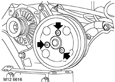
12. Unscrew the 3 bolts securing the power steering pump pulley and remove the pulley.
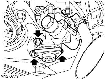
13. Unscrew the 3 bolts securing the power steering pump to the front plate, move the pump away and secure it.
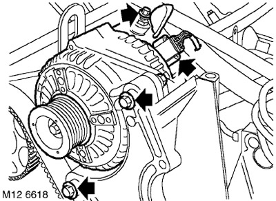
14. Remove the cover from the positive terminal of the generator, unscrew the nut and disconnect the battery bus from the generator.
15. Disconnect the connector from the generator.
16. Unscrew the lower bolt and the upper bolt with the nut securing the generator to the front plate of the engine.
17. Remove the generator.
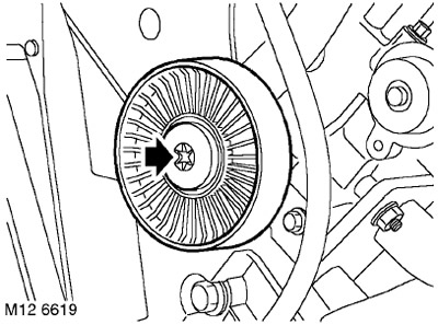
18. Loosen the bolt securing the intermediate roller to the front engine plate and remove the roller.
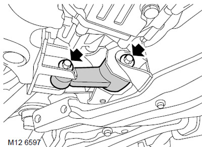
19. Loosen the bolt securing the lower engine mount cross member to the subframe.
20. Unscrew the bolt securing the lower crossmember to the sump support, release the lower engine crossmember from the sump support.
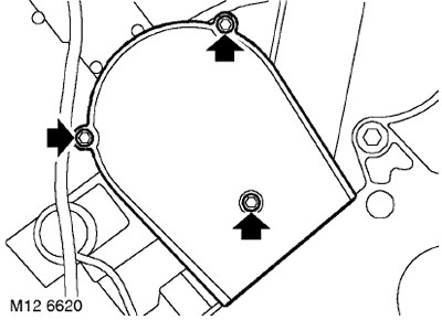
21. Unscrew the 3 bolts securing the front timing belt front cover on the right cylinder head and remove the cover.
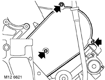
22. Unscrew the 3 bolts securing the front timing belt front cover on the left cylinder head and remove the cover.
23. Assemble the LRT-12-161 and LRT-12-199 fixtures together using a bolt.
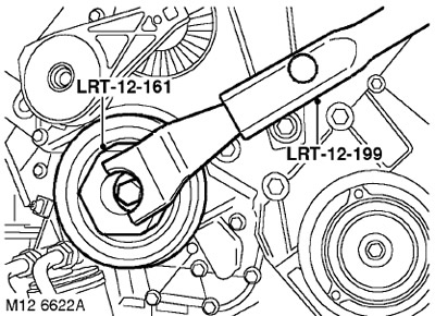
24. Install the LRT-12-161 with LRT-12-199 on the crankshaft pulley, loosen and remove the crankshaft pulley mounting bolt.
CAUTION: The crankshaft must not turn when performing the above procedure.
25. Remove the LRT-12-161 and LRT-12-199 tool from the crankshaft pulley and remove the pulley.
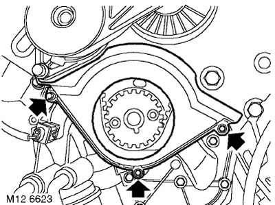
26. Unscrew the 3 bolts securing the lower part of the timing belt cover to the cylinder block and remove the cover.
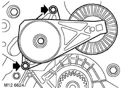
27. Unscrew the 2 bolts securing the accessory drive belt tensioner and remove the tensioner.
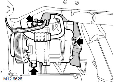
28. Mark the position of the heat shield on the air conditioning compressor, unscrew the 3 bolts securing the compressor to the front plate and to the cylinder block. Remove the cooling system compressor with the heat shield and set them aside.
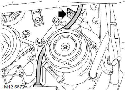
29. Unscrew the 2 bolts securing the oil dipstick housing to the cylinder block.
30. Press and hold the shoulders of the oil dipstick housing retainer and remove the oil dipstick housing from the pan.
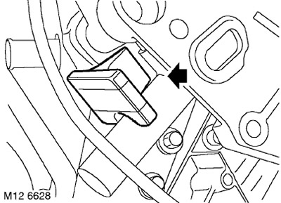
31. Remove the rubber plug located next to the timing belt tensioner.
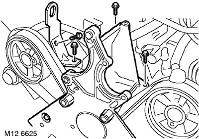
32. Unscrew the 3 bolts securing the front engine plate and lifting eye to the cylinder block.
33. Loosen the bolt securing the lifting eye to the right cylinder head and remove the eye.
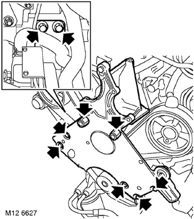
34. Unscrew the 2 bolts securing the transfer case bracket to the front engine plate.
35. Unscrew 5 bolts and 2 bolts with a mounting stud.
36. Carefully loosen and remove the front plate from the engine.
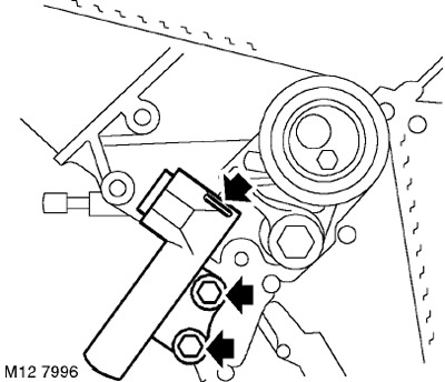
37. Insert a 1.5 mm diameter pin into the hole in the tension regulator housing and rod.
NOTE: If the holes in the housing and the rod do not line up, use a wide-blade screwdriver to move the tensioner lever to push the rod down until the holes line up and allow the pin to be inserted.
38. Loosen and discard the 2 bolts securing the belt tensioner to the cylinder block and remove the tensioner.
CAUTION: Be very careful and do not apply too much force when unscrewing the bolts. If the bolt is difficult to unscrew, first moisten it with a lubricant such as "liquid key". DO NOT LOOSE the Allen bolt that secures the tensioner pulley.
39. If the timing belt is intended to be used further, mark its direction of rotation before removing it.
40. Carefully, without using tools, release the belt from the gears and remove the belt.
CAUTION: Do not rotate the crankshaft with the timing belt removed and the cylinder heads installed.
CAUTION: The timing belt must be replaced if the cylinder head is to be removed, new gears, a new tensioner or a coolant pump is to be installed. Timing belts require careful handling and storage. Timing belts should be stored on their edge and with a bending radius of no less than 50 mm. Do not use a timing belt that has been twisted or folded in half, as the cord threads may be damaged. Do not use the timing belt if other wear particles (crumbs, threads) are found on the belt cover in addition to dust. Do not use the timing belt if the engine has partially seized. Belts that have covered 72,000 km must be replaced. Do not use timing belts whose surface is contaminated with oil or coolant. The cause of the contamination must be eliminated.
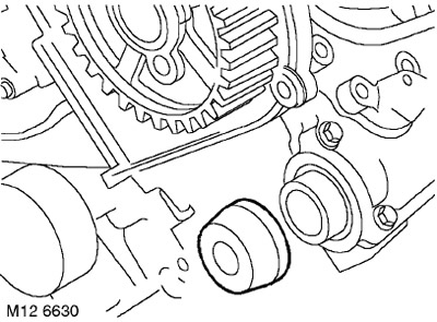
41. Remove and discard the right and left exhaust shaft seals.
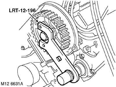
42. Install the LRT-12-196 drift onto the intake camshaft gears and onto the exhaust camshaft nose.
CAUTION: These mandrels must be installed whenever tightening or loosening the timing gear bolts to prevent damage to the camshafts.
43. Unscrew and dispose of the bolts securing the gears to the camshafts.
44. Remove the LRT-12-196 mandrels from the intake camshaft gears and from the exhaust camshaft noses.
45. Remove the camshaft drive gears with hubs.
Installation
NOTE: There is a possibility that after replacing the front or rear timing belt and setting the crankshaft pulley to the 'SAFE' position, the position marks on the rear timing gears may no longer align. This misalignment is acceptable provided the belt replacement procedure was carried out correctly.
1. Wipe the ring gears and their hubs, the crankshaft pinion, the tensioner roller and the coolant pump pulley.
ATTENTION: If the gears manufactured by sintering (powder metallurgy technology) have been in contact with oil for a long time, they must be soaked in a solvent and then washed in a clean solvent before installation. The porous structure of the sintered material absorbs oil, which, when released, will contaminate the timing belt.
2. Install the hubs onto the gears and install the gears onto the camshafts. Screw in new bolts and tighten them just enough so that the gears can rotate without wobbling.
3. Place the timing belt on the crankshaft gear.
NOTE: To prevent the belt from slipping off the crankshaft gear when installing, it must be pressed down with some object inserted between the belt and the protective protrusion on the oil pump housing.
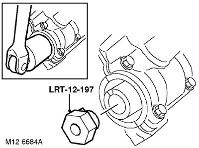
4. Install the LRT-12-197 tool into each exhaust camshaft, one at a time.
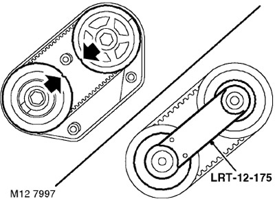
5. With the help of a partner, slightly turn the exhaust camshaft until the marks on the right and left rear gears align.
6. Remove the LRT-12-197 drift from both exhaust camshafts.
7. Install LRT-12-175 mandrels on the left and right rear gears.
8. Rotate the front gears of both intake shafts clockwise when looking at the front of the engine.
9. Using only your hands, without using any tools, put on the toothed belt, laying it counterclockwise. In this case, the laid part of the belt should be kept as taut as possible, the toothed wheels turn counterclockwise only so much that the belt can be put on.
CAUTION: The gears must not be rotated counterclockwise more than one tooth.
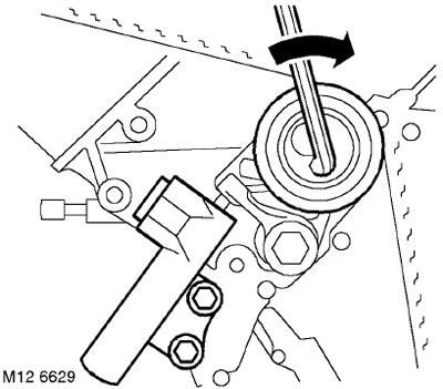
10. Using an Allen key, tighten the belt with the tensioner roller.
11. With the help of a partner, install the tension regulator, screw in the new mounting bolts and tighten them to a torque of 25 Nm.
CAUTION: Check that the tension adjuster rod contacts the tensioner lever.
12. Remove the LRT-12-175 tools from the rear gears.
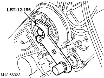
13. Install the LRT-12-196 drift onto both intake camshaft sprockets and onto the exhaust camshaft nose.
CAUTION: These mandrels must be installed whenever tightening or loosening the timing gear bolts to prevent damage to the camshafts.
14. Tighten the front gear mounting bolts:
- Stage 1: 27 Nm
- Step 2: 90° turn
15. Remove the LRT-12-196 mandrels from the intake camshaft gears and the exhaust camshaft noses.
16. Remove the timing belt stopper from under the crankshaft gear.
17. Remove the pin from the timing belt tensioner.
18. Insert the rubber plug.
19. Remove the LRT-12-232 pin.
20. Wipe the exhaust camshaft nose sealing areas and install new seals.
CAUTION: The sealing lips and the mating sealing surface must be clean and dry.
21. Reinstall the front engine plate. Screw in the bolts, but do not tighten them completely.
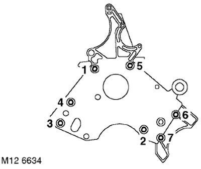
22. Screw in the bolts securing the transfer case bracket to the front engine plate, but do not tighten them completely.
23. Tighten the bolts in the sequence shown in the figure:
- Bolt No.1: 25 Nm
- Bolt No.5: 45 Nm
- Bolts No.2, 3, 4, 6 and 7 - 85 Nm
24. Install the lifting eye on the engine, screw in the bolts securing the lifting eye and the front plate of the engine to the cylinder block and to the right cylinder head. Tightening torque for M10 bolts - 45 Nm, for M8 bolts - 25 Nm.
25. Wipe the end of the dipstick housing.
26. Install the oil dipstick, screw in the bolt and tighten it to a torque of 9 Nm.
27. Install the cooling system compressor on the front engine plate and on the cylinder block, align the holes in the heat shield, screw in the bolts and tighten them to a torque of 25 Nm.
28. Wipe the bottom of the front timing belt cover.
29. Install the lower timing belt cover and tighten the mounting bolts to 9 Nm.
30. Wipe the crankshaft pulley.
31. Install the crankshaft pulley onto the crankshaft pinion, making sure that the notch on the pulley is aligned with the protrusion on the pinion.
32. Screw in the pulley mounting bolt with the washer, install the LRT-12-161 with LRT-12-199 tool on the crankshaft pulley. Tighten the pulley mounting bolt to 160 Nm.
33. Remove the LRT-12-161 and LRT-12-199 tool from the crankshaft pulley and remove the pulley.
34. Wipe the accessory drive belt tensioner.
35. Install the accessory drive belt tensioner, screw in the bolts and tighten them to a torque of 25 Nm.
36. Wipe the left and right front timing belt covers.
37. Replace the left and right front timing belt covers, install the bolts and tighten them to 4 Nm.
38. Wipe the intermediate roller, install the roller on the front engine plate and tighten the mounting bolt to 45 Nm.
39. Install the generator on the front plate of the engine.
40. Insert the generator mounting bolt to the front engine plate, tighten the nut and tighten to 45 Nm.
41. Connect the generator connector.
42. Connect the battery busbar to the generator terminal, tighten the nut to 8 Nm.
43. Install the power steering pump on the front plate, screw in the bolts and tighten them to a torque of 25 Nm.
44. Install the power steering pump on the front engine plate, screw in the bolt and tighten it to 25 Nm.
45. Wipe the power steering pump pulley and mating surfaces.
[The source of the article is located on the website: LRMAN.ru]
46. Install the pulley on the power steering pump, screw in the bolts and tighten them to a torque of 9 Nm.
47. Install the lower cross member on the tray bracket, screw in the bolts and tighten them to a torque of 100 Nm.
48. Tighten the lower cross member to subframe mounting bolt to a torque of 100 Nm.
49. Wipe the left rear timing belt cover.
50. Replace the left rear timing belt cover, install the bolts and tighten them to 4 Nm.
51. Wipe the right rear timing belt cover.
52. Replace the right rear timing belt cover, install the bolts and tighten them to 4 Nm.
53. Install the heat shield, screw in the bolts and tighten the M6 bolts to 9 Nm and the M8 bolts to 25 Nm.
54. Install the intake receiver.
COLLECTORS AND EXHAUST SYSTEM: MOD. K, V6 engine, REPAIR WORK, Intake manifold seals: vehicles manufactured before May 2003.
COLLECTORS AND EXHAUST SYSTEM: MOD. K, V6 engine, REPAIR WORK, Intake manifold seals: vehicles manufactured after May 2003.
55. Reinstall the right wheel and tighten the nuts to a torque of 115 Nm.
56. Install the accessory drive belt.
ENGINE STARTING AND BATTERY CHARGING SYSTEM, REPAIR WORK, Attachment drive belt - KV6 engine.
Comments on this article