Contents: Dismantling ⇩ Installation ⇩
Dismantling
1. Disconnect the negative battery terminal.
2. Drain the coolant from the engine.
COOLING SYSTEM: MOD. K, KV6 engine, ADJUSTMENTS, Draining coolant, flushing and filling the system.
3. Remove the intake receiver.
COLLECTORS AND EXHAUST SYSTEM: MOD. K, V6 engine, REPAIR WORK, Intake manifold seals: vehicles manufactured before May 2003.
4. Remove the left exhaust manifold gasket.
COLLECTORS AND EXHAUST SYSTEM: MOD. K, V6 engine, REPAIR WORK, Left exhaust manifold gasket: except for North American market countries.
COLLECTORS AND EXHAUST SYSTEM: MOD. K, V6 engine, REPAIR WORK, Left exhaust manifold gasket(s): North American market countries.
5. Remove the timing belt.
ENGINE KV6 - MODIFICATION K, Camshafts of the left cylinder head, Timing belt.
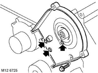
6. Unscrew the 4 bolts securing the rear cover of the front timing belt to the left cylinder head and remove the cover.
7. Remove the left cylinder head valve cover gasket.
ENGINE KV6 - MODIFICATION K, Left cylinder head camshafts, Left cylinder head valve cover gasket: up to May 2003.
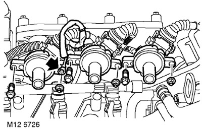
8. Unscrew the 3 nuts and 3 bolts securing the ignition coils to the left intake manifold and disconnect the ground wire of the coils, if provided.
9. Remove the ignition coils and set them aside.
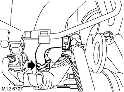
10. Loosen the clamp, disconnect the steam outlet hose from the intake manifold and move the hose to the side.
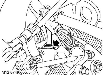
11. Press the shoulders and remove the ventilation hose from the left intake manifold.
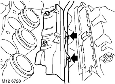
12. Disconnect the right-hand injector harness either from the injector protective cover (if provided) or from the lugs on the fuel rail.
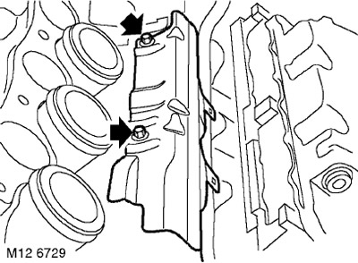
13. Unscrew the 2 bolts securing the injector protective cover (if provided) and the fuel rail to the right intake manifold and remove the cover.
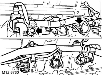
14. Unscrew the 2 bolts securing the fuel rail to the left intake manifold.
15. Release the injectors from the manifolds and carefully place the ramp with the injectors aside.
CAUTION: Always plug the fittings and holes to protect the system from dirt.
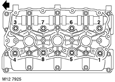
16. In the sequence shown in the figure, loosen and unscrew the 8 cylinder head mounting bolts.
17. With the help of a partner, remove the cylinder head.
CAUTION: Place the cylinder head on wooden blocks.
18. Remove and discard the cylinder head gasket.
Do not rotate the crankshaft with the cylinder head installed (and timing belt removed).
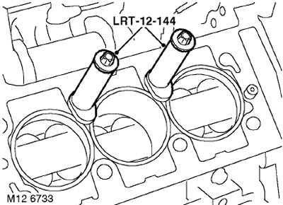
19. Install the LRT-12-144 fasteners onto the cylinder liners and tighten them with the cylinder head fastening bolts.
CAUTION: The base of the cylinder liner fasteners must not protrude above the cylinder bore.
Installation
1. Wipe the lower surface of the cylinder head.
CAUTION: Use a special cleaning liquid and a plastic scraper.
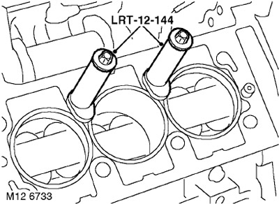
2. Unscrew the bolts from the LRT-12-144 cylinder liner fasteners and remove the fasteners.
CAUTION: Do not rotate the crankshaft.
3. Clean the top surface of the cylinder block and the holes for the mounting pins.
4. Wash the cylinder head mounting bolts and wipe them dry.
5. Lightly lubricate the threaded portion and bolt heads with clean engine oil.
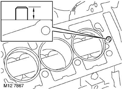
6. Check that the protrusion of the pins above the plane of the block is within 10-11 mm. Replace the pins if the protrusion does not correspond to the values specified above.
7. Install a new cylinder head gasket onto the cylinder block with the 'TOP' mark facing upwards.
8. With the help of a partner, place the head on the cylinder block and carefully install the left intake manifold onto the right.
9. Carefully insert the cylinder head mounting bolts, DO NOT LOOSE THE BOLTS TO FALL INTO THEIR SOCKETS. Tighten the bolts by hand.
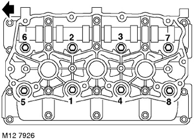
10. Tighten the cylinder head bolts in the sequence shown in the figure.
- Stage 1: 25 Nm
- Step 2: Tighten to 25 Nm in the same sequence
- Step 3: Tighten to 25 Nm in the same sequence
- Step 4 - Using an angle torque wrench, tighten the bolts in the same sequence by 180°
11. Install the left cylinder head valve cover gasket.
ENGINE KV6 - MODIFICATION K, Left cylinder head camshafts, Left cylinder head valve cover gasket: up to May 2003.
12. Remove the O-rings from the injectors and discard them.
13. Wipe the injectors and their seats in the fuel rail.
14. Lubricate new O-rings with castor oil and install them on the injectors.
15. Install the fuel rail assembly and secure the injectors in the intake manifolds.
16. Install the injector guard (if provided) on the right fuel rail and secure the injector harness to the clips on the protective cover.
17. Screw in the bolts securing the fuel rail to the intake manifold and tighten them. Tightening torque 9 Nm.
18. Install the camshaft position sensor mounting bracket, screw in the bolt and tighten to 9 Nm.
19. Connect the camshaft position sensor connector and secure it to the bracket.
20. Connect the ventilation hose to the left intake manifold.
21. Connect the cooling system vapor bleed hose to the intake manifold and secure it with a clamp.
Original article on the web portal [lrman.ru]
22. Install the ignition coils to the left intake manifold.
23. Install the ground wire, install the harness mounting bolts to the left intake manifold and tighten to 9 Nm.
24. Install the high voltage wire bracket, screw in and tighten the special bolt.
25. Connect the high tension wires to the spark plugs and secure the wires in the bracket.
26. Clean the rear timing belt cover mounting bolts and apply STC 50552 sealant to the first three threads.
27. Install the rear belt cover, screw in the bolts and tighten them to a torque of 9 Nm.
28. Install the timing belt.
ENGINE KV6 - MODIFICATION K, Camshafts of the left cylinder head, Timing belt.
29. Install the left exhaust manifold gasket.
COLLECTORS AND EXHAUST SYSTEM: MOD. K, V6 engine, REPAIR WORK, Left exhaust manifold gasket: except for North American market countries.
COLLECTORS AND EXHAUST SYSTEM: MOD. K, V6 engine, REPAIR WORK, Left exhaust manifold gasket(s): North American market countries.
30. Install the intake receiver.
COLLECTORS AND EXHAUST SYSTEM: MOD. K, V6 engine, REPAIR WORK, Intake manifold seals: vehicles manufactured before May 2003.
31. Fill the cooling system with coolant.
COOLING SYSTEM: MOD. K, KV6 engine, ADJUSTMENTS, Draining coolant, flushing and filling the system.
32. Check the oil level and top up if necessary.
MAINTENANCE, Engine Oil and Oil Filter - KV6.
Comments on this article