Contents: Clutch housing - type A gearbox ⇩ Clutch housing - type B gearbox ⇩ Clutch housing - type C gearbox ⇩ Clutch housing - type D gearbox ⇩ Gearshift housing - Type A gearbox ⇩ Shift rod housing - Type A gearbox ⇩ Gearshift housing - type B gearbox ⇩ Rod leash - Type A gearbox ⇩ Rod leash - Type B gearbox ⇩ Shift mechanism - type C gearbox ⇩ Shift mechanism - D-type gearbox ⇩ Rod linkage - D-type gearbox ⇩ Rear housing - gearbox type A and B ⇩ Rear housing - Type C gearbox ⇩ Rear housing - D-type gearbox ⇩ Removal the fifth and reverse gears ⇩ Removal the secondary and…⇩ Disassembling the secondary shaft ⇩ Main crankcase ⇩ Disassembling the front gearbox cover ⇩ Disassembling the intermediate plate ⇩ Disassembling the rear case -…⇩ Disassembling the rear case -…⇩ Assembly ⇩ Disassembling the gearshift…⇩ Examination ⇩ Assembly ⇩ Disassembling the piston housing -…⇩ Assembly ⇩ Disassembling the gearshift…⇩ Assembly ⇩ Disassembling the gearshift…⇩ Assembly ⇩ Disassembling the shift mechanism -…⇩ Transfer case shift mechanism - type…⇩ Examination ⇩ Assembly ⇩ Synchronizer - repair ⇩ Assembly ⇩ Checking the clearance between the…⇩ Primary shaft - repair ⇩ Secondary shaft - check ⇩ Intermediate shaft - repair ⇩ Secondary shaft - assembly ⇩ Reverse idler gear - installation ⇩ Shift forks - inspection ⇩ Shift forks - installation ⇩
Clutch housing - type A gearbox
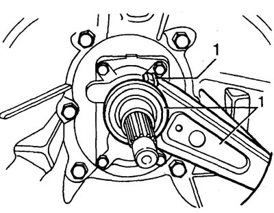
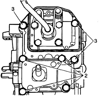
1. If installed: Remove and discard the clips securing the clutch release fork to the release bearing, remove the bearing and fork.

2. Unscrew the two bolts securing the release bearing guide.
3. Unscrew the six clutch housing mounting bolts and remove the housing.
Note: Installation using guide pins.
Clutch housing - type B gearbox
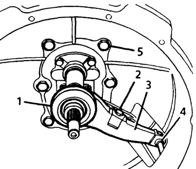
1. Remove the release bearing.
2. Unscrew the bolt securing the fork spring clamp and remove the clamp.
3. Remove the clutch fork.
4. Remove the clutch slave cylinder rod retainer.
5. Unscrew the six clutch housing mounting bolts and remove the housing.
Note: Installation using guide pins.
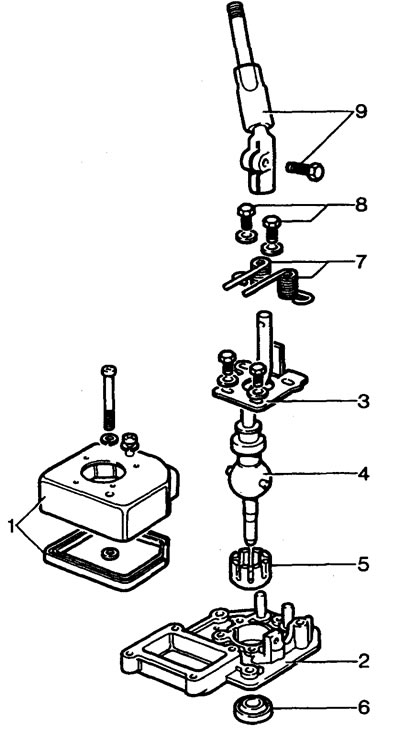
The gear shift mechanism is a type B gearbox. 1 - gearshift mechanism housing with gasket, 2 - rod housing, 3 - adjusting plate, 4 - lower part of gearshift lever, 5 - bushing, 6 - oil seal, 7 - springs, 8 - spring fixing bolts, 9 - upper part of gearshift lever and mounting bolt.
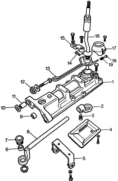
The gear shift mechanism is a type C gearbox. 1 - gear shift housing, 2 - wire, 3 - linkage fixing bolt, 4 - lower cover, 5 - bracket, 6 - ball pin, 7 - pin seat, 8 - rod, 9 - rod bushing, 10 - spacer, 11 - support bushing, 12 - support cushion, 13 - spring, 14 - spring guide, 15 - spring fixing bracket, 16 - gear shift lever, 17 - gear shift lever cover, 18 - nylon pin, 19 - damper spring.
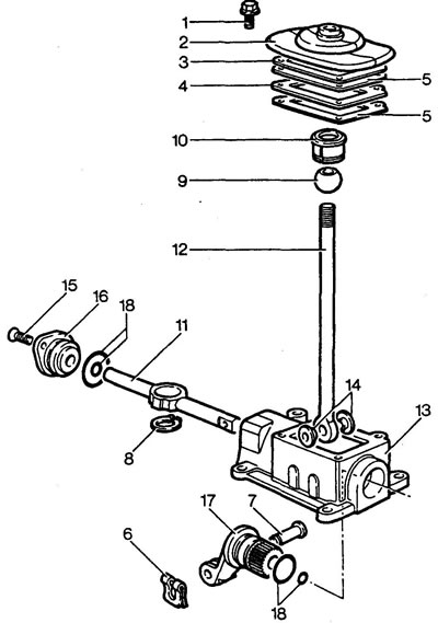
The transfer case shift mechanism is a type A gearbox. 1 - boot frame mounting bolt, 2 - boot, 3 - mounting support plate, 4 - spacer, 5 - gaskets, 6 - clip, 7 - pin, 8 - seat retaining ring, 9 - lever ball joint, 10 - seat, 11 - cross shaft, 12 - shift lever, 13 - shift mechanism housing, 14 - bushings, 15 - rod thrust cover fixing screws, 16 - rod thrust cover, 17 - shift fork, 18 - sealing rings
Clutch housing - type C gearbox
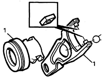
1. Pull the clutch release lever until the locks are released, remove the fork and bearing.
2. Unscrew the six clutch housing mounting bolts and remove the housing.
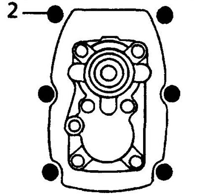
Note: The two longest bolts (with washers) are installed in the guide pin holes.
Clutch housing - type D gearbox
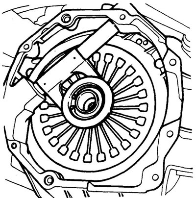
Note: Type D gearboxes have a standard adapter that allows the gearbox to be mounted to the clutch housings of V8 and diesel engines. The figure shows the adapter mounted on the engine (gearbox removed).
1. Unscrew the two bolts securing the release bearing guide. Remove the guide.
2. Unscrew the six clutch housing mounting bolts. Remove the crankcase.
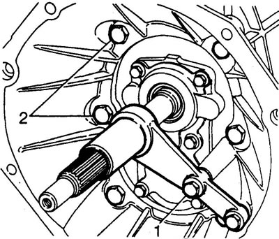
Gearshift housing - Type A gearbox
1. Unscrew the four bolts securing the shift mechanism housing and remove the housing.
Note: Installation using guide pins.
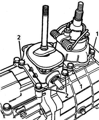
2. Unscrew the four bolts securing the transfer case shift mechanism housing and remove the housing.
Shift rod housing - Type A gearbox
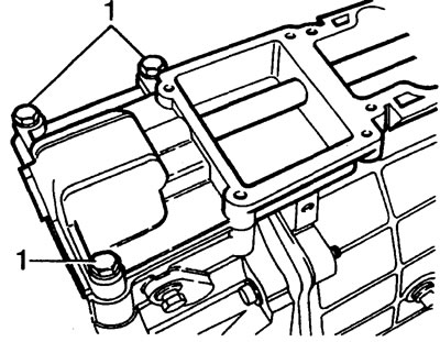
1. Unscrew the three bolts securing the rod housing, remember the locations of the bolts.
Note: Installation using guide pins.
Gearshift housing - type B gearbox
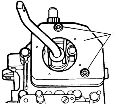
1. Unscrew the two screws securing the shift mechanism housing cover, remove the cover and gasket.
2. Unscrew the four bolts securing the transfer case shift mechanism housing and remove the housing.
3. Unscrew the three bolts securing the shift mechanism housing, remember the locations of the bolts, and remove the housing.
Note: Installation using guide pins.
Rod leash - Type A gearbox
1. Loosen the mounting screw, do not reinstall the screw.
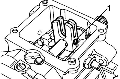
2. Move the rod forward, remove the leash.
Rod leash - Type B gearbox
1. Loosen the mounting screw, do not reinstall the screw.
2. Move the rod forward, remove the leash.
Shift mechanism - type C gearbox
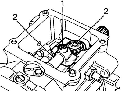
1. Remember the order of installing the support cushions and washers, unscrew the two bolts securing the shift mechanism housing.
2. Unscrew the two bolts securing the shift mechanism housing bracket.
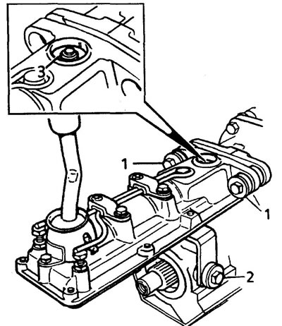
3. Separate the housing from the gearbox housing, remove the shift rod from the pin.
Shift mechanism - D-type gearbox
1. Unscrew the four bolts securing the shift mechanism housing.
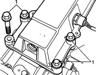
2. Separate the housing from the gearbox housing.
Rod linkage - D-type gearbox
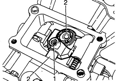
1. Unscrew the leash mounting screw, do not reinstall the screw.
2. Move the rod forward, remove the leash.
Rear housing - gearbox type A and B
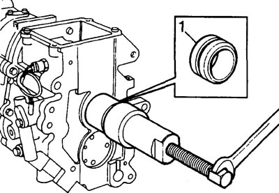
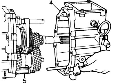
1. Screw the M12 bolt into the threaded hole of the secondary shaft and, using tools LRT-37-010 and LRT-37-009, remove the oil seal bushing.
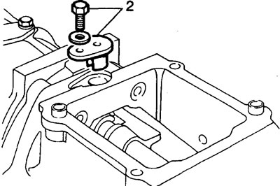
2. Remove the reverse gear locking sleeve holder.
3. Unscrew the ten rear crankcase mounting bolts, remember the installation locations of the long bolts.
4. Place a container to collect the oil under the place where the crankcases are connected and separate the rear gearbox housing from the main one.
5. Remove the oil filter.
6. Secure the intermediate plate to the main crankcase with two M8 - 35 mm bolts.
Rear housing - Type C gearbox
1. Unscrew the nut securing the pin to the rod and remove the pin. Do not reinstall the nut.
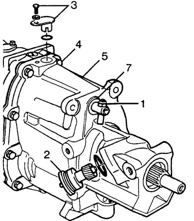
2. Carefully remove the speedometer drive pinion housing and sealing ring.
3. Remove the reverse gear locking sleeve holder and sealing ring.
4. Unscrew the ten bolts securing the rear gearbox housing, remember the locations of the bolts.
5. Using a plastic hammer, remove the rear crankcase from the guide pins.
6. Remove the rear crankcase.
Note: The speedometer drive pinion may be installed on the secondary shaft with significant interference, which may make removal of the rear case difficult. In this case, place a suitable wooden block between the main and rear gearbox housings and, using a lever, carefully separate the parts.
7. Remove the piston rod seal; do not reinstall the seal.
8. Secure the intermediate plate to the main crankcase with two M8 - 35 mm bolts.
Rear housing - D-type gearbox
1. Remove the reverse gear locking sleeve holder.
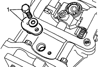
2. Unscrew the ten rear crankcase mounting bolts, remember the installation locations of the long bolts.
3. Place a container under the crankcase connector to collect the oil.
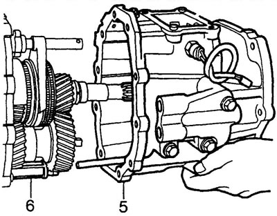
4. Separate the rear gearbox housing from the main one using a plastic hammer.
5. Remove the rear crankcase.
6. Remove the oil filter.
Removal the fifth and reverse gears
1. Using a suitable puller, remove the inner bearing race from the intermediate shaft.
2. Holding the 5th gear pinion with the LRT-37-023 locking tool, loosen the pinion mounting nut.
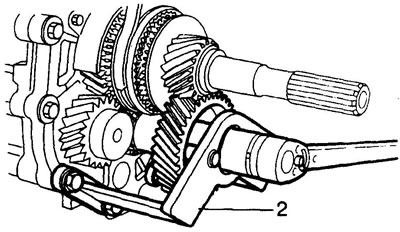
3. Remove the thrust spacer segments and the retaining ring, after knocking out the pin.
4. Late models: Remove the 5th gear retaining ring.
5. Remove the 5th gear.
6. Using tools LRT-37-009 and LRT-37-024, remove the secondary shaft rear bearing ring.
7. Unscrew the M12 bolt from the end of the secondary shaft.
8. Remove the 5th gear gear together with the synchronizer ring.
9. Remove the 5th gear needle bearing.
10. Remove the 5th gear synchronizer clutch retaining ring.
11. By rotating the reverse gear locking sleeve, remove the fifth and reverse gear synchronizer sleeve together with the shift fork and locking sleeve.
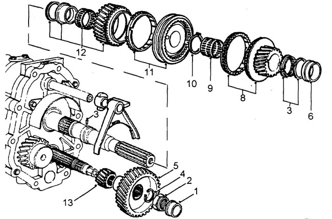
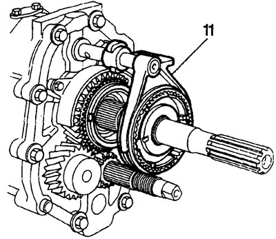
12. Remove the reverse gear from the secondary shaft together with the needle bearing and bushing, remember the thickness of the adjusting washer installed between the reverse gear and the intermediate plate of the gearbox.
13. Remove the reverse gear from the intermediate shaft.
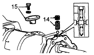
14. Unscrew the plug from the intermediate plate, remove the spring and the ball that secures the rod.
15. Unscrew the two bolts securing the reverse gear locking sleeve holder and remove the holder.
Removal the secondary and intermediate shafts
1. Align the shift rod pin with the slot in the transmission intermediate plate and, using a wooden block and a hammer, pry the intermediate plate away.
Editor's note: Remove the two bolts securing the plate to the main crankcase.
2. Select the spring and the ball of the rod retainer, remove the bearings and adjusting washers.
3. Remove the secondary and intermediate shafts and the shift rod together.
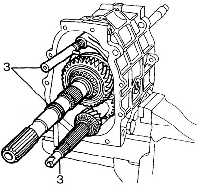
4. Remove the input shaft and the fourth gear synchronizer locking ring (if it hasn't been removed yet with the secondary shaft).
Disassembling the secondary shaft
1. Using the LRT-99-002 puller or its equivalent, remove the bearing from the secondary shaft, creating a stop under the first gear pinion.
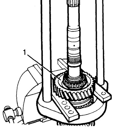
2. Remove the first gear, needle bearing and synchronizer rings from the secondary shaft.
3. Remove the 1/2 gear synchronizer sleeve, synchronizer rings, 2nd gear and needle bearing.
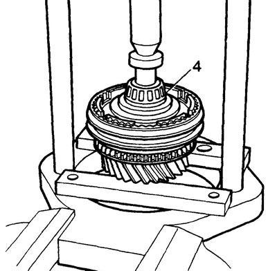
4. Turn the secondary shaft over. Using the LRT-99-002 puller or its equivalent, remove the bearing from the secondary shaft, creating a stop under the third gear gear.
5. Remove the spacer, 3/4 synchronizer sleeve, synchronizer rings, 3rd gear gear and needle bearing.
Main crankcase
Clean and wash all components. Check the crankcase for damage, cracks and the condition of the threaded holes.
1. Install the filler plug.
2. Install the drain plug and new sealing washer.
Disassembling the front gearbox cover
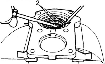
1. Remove the front cover and bearing races. Check that the snap rings are installed correctly.
2. Remove the oil seal; there is no need to install a new oil seal at this stage of the repair.
Disassembling the intermediate plate
1. Remove the bearing races and adjusting washers and check their condition.
2. Check the shift rod hole for wear.
3. If necessary, remove the oil deflector plate.
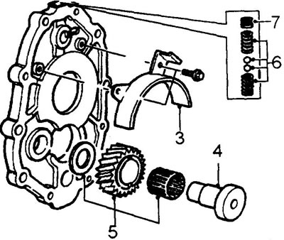
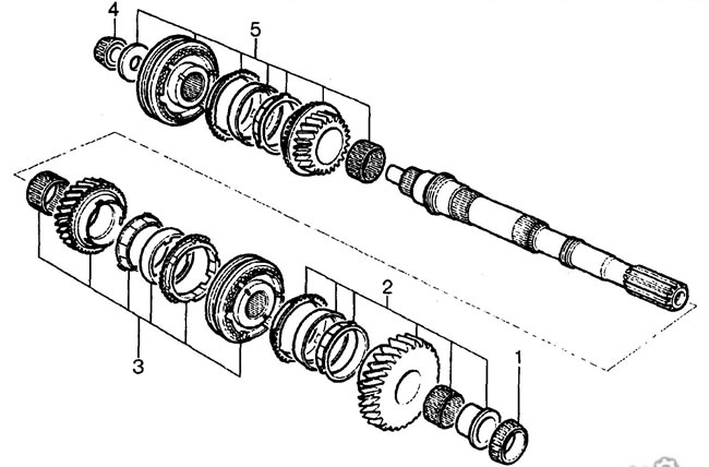
4. Using a suitable puller, remove the reverse gear idler shaft. Check for wear and damage.
5. Remove the idler gear, needle bearing and washer, check for wear and damage.
6. Check the springs and balls of the rod retainer for deformation and damage.
7. Check the condition of the thread under the locking plug.
Note: If the plug thread condition is satisfactory, it can be reinstalled.
Disassembling the rear case - gearbox types A and B
1. Check the condition of the threaded holes and seats of the crankcase.
2. Unscrew the three screws securing the oil pump and remove the pump.
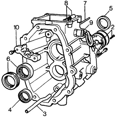
3. Remove the oil pump tube. Check that the oil passage is not blocked.
4. Knock out the intermediate shaft roller bearing.
5. Remove the secondary shaft rear oil seal.
6. Knock out the secondary shaft bearing and oil supply ring.
7. Remove the reverse gear lock pawl shaft.
8. Remove the pawl and spring.
9. Unscrew the reverse light switch and remove the gasket.
10. Remove the guide.
11. Check all components for damage.
Disassembling the rear case - gearbox types C and D
Disassembly is carried out in the same way as for type A and B gearboxes, including the following:
- 1. Check the speedometer drive gears for damage, replace if necessary.
- 2. Check the 5th gear guide sleeve slot for wear.
Caution: The rear secondary shaft oil seal for type C and D transmissions differs from the oil seal installed in type A and B transmissions. When removing the oil seal, be careful not to damage the mounting seat.
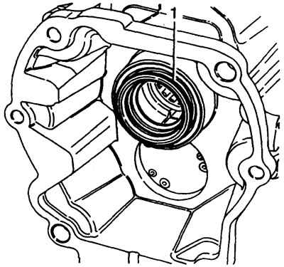
Note: Rear case shown is type D transmission.
Assembly
1. Lubricate the oil pump centering flange with oil.
2. Replace the sealing ring, install the oil pump into the crankcase.
Note: The TOP mark on the pump must point towards the top of the crankcase.
3. Using light taps, firmly seat the pump in the seat.
Note: Make sure that the holes for installing the fasteners on the pump and crankcase are aligned.
4. Install the new secondary shaft support bearing.
5. Using the LRT-37-014 tool, install the new secondary shaft rear oil seal
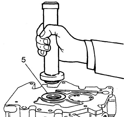
6. Install the new intermediate shaft bearing.
7. Install the oil supply ring, aligning the hole in the ring with the groove in the housing.
8. Check the guide, if it is damaged, replace it.
9. Install the reverse light switch and tighten to 24 Nm.
10. Install the spring and reverse gear lock pawl.
11. Apply adhesive and insert the pawl axle.
12. Install the oil pipe with the bend facing upwards.
Disassembling the gearshift mechanism - gearbox
Type A gearbox
1. Using a suitable piece of tubing, pry both ends of the spring away from the shift lever ball stud pins.
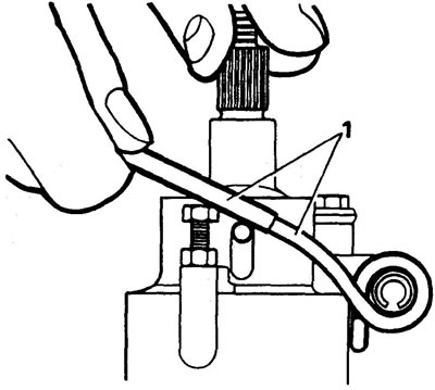
2. Loosen the lock nuts and remove the spring adjusting screws.
3. Knock out the pin and remove the spring.
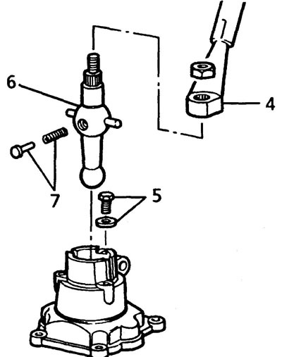
4. Disconnect the upper part of the shift lever.
5. Unscrew the bolt and washer securing the lower part of the shift lever.
6. Carefully remove the lower part of the shift lever from the housing. In this case, the release of the compression force of the damper spring holding the nylon finger of the lever should be carried out gradually. Caution: Sudden release of spring compression may result in injury.
7. Remove the pin and damper spring.
8. Wash all parts.
Examination
1. Check the condition of the ball joint at the bottom of the shift lever. If there is wear, replace the lever.
Caution: Replace the support seat installed in the shift rod housing at the same time as the lever.
2. Check the condition of the nylon pin and damper spring.
3. Check the condition of the shift lever retaining springs.
Assembly
1. Lubricate the ball joint of the lever with grease, install the damper spring and pin.
2. Insert your finger into the lever and install the lever into the housing.
3. Install the lower arm mounting bolt and tighten the bolt to 15 Nm.
4. Attach the upper part to the lower part of the lever.
5. Install the pin into the housing and the lower part of the lever.
6. Install the retaining springs, adjusting screws and lock nuts.
7. Using a suitable piece of tubing, thread both ends of the spring over the lever pins.
Note: Do not adjust the spring installation at this time.
Disassembling the piston housing - type A gearbox
1. Unscrew the screw securing the journal to the rod.
2. Remove the lever support seat retaining ring and remove the seat.
3. Loosen the lock nut of the fifth gear locking screw and remove the screw.
Note: Please select the correct adjusting washers.
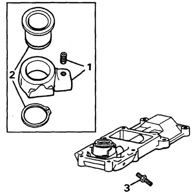
4. Unscrew the plug.
5. Unscrew the screw securing the leash to the rod and remove the leash.
6. Remove the stem together with the sealing ring. Remove and discard the ring.
7. Remove the retaining ring that secures the rollers and the pin on the leash.
8. Remove the pin and take off the rollers.
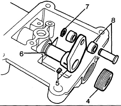
9. Check components for wear and damage.
Assembly
1. Lubricate the piston rod and new O-ring with oil.
2. Install the ring on the stem.
3. Install the rod into its body.
4. Install the rollers and pin onto the leash and install a new retaining ring.
Note: The head of the pin must be facing the direction opposite to the bosses on the body of the rod.
5. Install the leash on the rod.
6. Apply Loctite 270 locking adhesive to the leash fixing screw and install the screw.
7. Apply Loctite 270 locking adhesive to the plug threads and install the plug.
8. Lubricate the seat of the ball joint of the shift lever with grease.
9. Install the saddle into the journal and secure with a retaining ring.
10. Install the journal onto the rod.
11. Apply Loctite 270 locking adhesive to the threads of the trunnion retaining screw, install the screw and tighten it.
12. Install the fifth gear locking screw, but do not tighten the lock nut.
Note: The lock screw is adjusted during gearbox assembly.
Disassembling the gearshift mechanism - Type B gearbox
1. Loosen the bolts securing the shift lever retaining springs.
Caution: To avoid injury, hold both springs with pliers.
2. Remove both springs.
3. Unscrew the remaining lever mounting bolts.
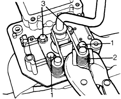
4. Remove the plastic sleeve. Do not reinstall the bushing.
5. Remove the sealing ring.
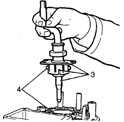
6. Check all components for wear and damage.
Assembly
1. Lubricate the ball and the lever support pins with grease.
2. Lubricate the new plastic bushing with grease and install it into the shift housing.
Caution: Align the grooves in the sleeve and the housing.
3. Lubricate the new O-ring with oil.
4. Install the ring using a suitable mandrel.
5. Install the lever so that its fingers fit into the slots of the sleeve and housing.
6. Install the lever retaining spring adjusting plate.
7. Apply Loctite 270 locking adhesive to the threads of the two short spring mounting bolts.
8. Install the bolts into the front of the adjusting plate and tighten to 25 Nm.
9. Place the long end of the spring onto the shift lever.
10. Apply Loctite 270 locking adhesive to the threads of the two long spring mounting bolts.
11. Using pliers, place the short ends of the spring onto the bolts from the outside.
Caution: Be careful, as spring release may cause injury.
12. Install the bolt and washer (the spring should lie under the washer), tighten the bolt to 25 Nm.
13. Repeat the procedures for the other spring.
Disassembling the gearshift mechanism - Type C gearbox
1. Remove the two bolts and two screws securing the retaining spring pressure plates.
2. Remove the pressure plates, guides and spring.
3. Unscrew the four bolts securing the bottom cover and remove the cover.
4. Unscrew the bolt securing the shift lever sphere cover and remove the cover.
5. Remove the lever, damper spring and pin.
6. Unscrew the clamping bolt securing the rod arm.
7. Remove the rod.
8. Wash and inspect the parts.
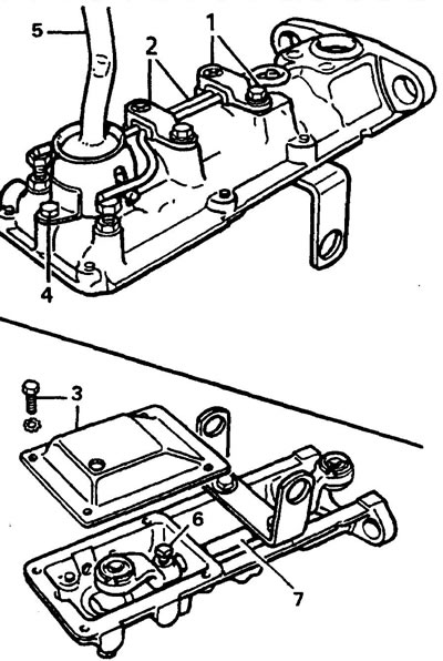
Assembly
1. Lubricate the piston rod and bushings with grease. Install the stem into the body.
2. Lubricate the ball joint and lever pins with grease.
3. Install the leash onto the rod, install and tighten the clamp bolt.
4. Install the damper spring and pin into the lever.
5. Install the lever, making sure the damper spring and pin are in place.
6. Install the lever cover.
Note: There is no need to install the bottom cover now.
7. Loosen the lever retaining spring adjusting bolt lock nut.
8. Install the spring, pressure plates and guides.
9. Install and tighten the clamp plate mounting bolts and screws.
Note: The final adjustment of the retaining spring is carried out after installing the shift mechanism on the gearbox.
Disassembling the shift mechanism - D-type gearbox
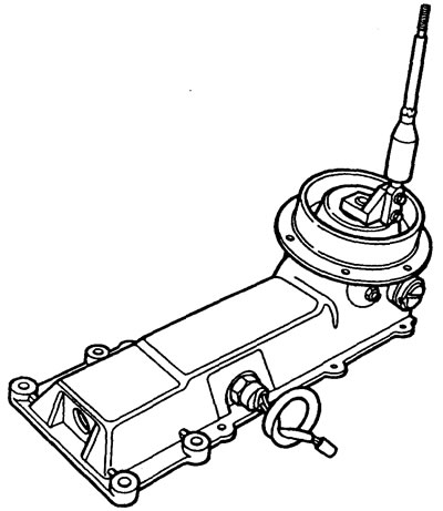
Note: the shift mechanism installed on the D-type gearbox is not repairable and is replaced as an assembly in the event of a malfunction.
Transfer case shift mechanism - type A gearbox
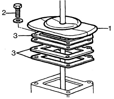
1. Lift the transfer case shift lever boot.
2. Unscrew the four bolts securing the boot support plate.
3. Remove the backing plate and spacers.
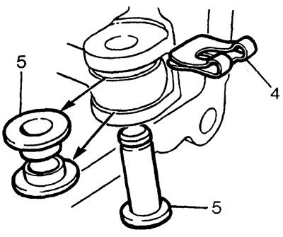
4. Remove the shift fork pin retaining clip. Do not reinstall the clip.
5. Remove the pin and two bushings. Do not reinstall the bushings.
6. Remove the retaining ring from the ball joint seat of the lever.
7. Remove the lever, ball joint and joint seat.
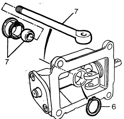
8. Unscrew the two screws securing the housing cover. Remove the lid
9. Remove the two sealing rings from the lid.
10. Remove the cross shaft.
11. Remove the shift fork and two shift fork seals.
12. Wash all parts.
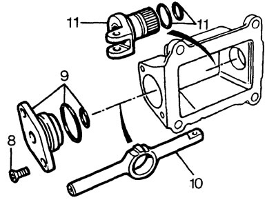
Examination
1. Check the condition of the boot. Replace if necessary.
2. Check the ball joint of the lever and its seat. Replace as needed and only in pairs.
3. Check the shift cam, cross shaft and cover for wear
Assembly
1. Lubricate the fork sealing rings with transmission oil. Install the plug into the housing.
2. Lubricate the cross shaft with grease. Install the shaft into the housing and fork. The long end of the shaft should fit into the fork.
3. Lubricate the cover sealing rings with transmission oil.
4. Install the cover on the cross shaft, tighten the mounting screws.
5. Install the ball joint and ball joint seat onto the shift lever. The groove of the seat must face the cross shaft.
6. Lubricate the hinge and seat with grease. Install the joint and seat into the cross shaft, secure the seat with a new retaining ring.
7. Install two new bushings into the lever. Place the lever into the shift fork.
8. Install the lever mounting pin and the new pin retaining clip.
9. Install the gaskets and the boot support plate. Tighten the mounting bolts to 15 Nm.
10. Install the boot.
Synchronizer - repair
1. Remove the spring half rings of the crackers from both sides of the synchronizer.
2. Remove the breadcrumbs. Remove the sleeve from the synchronizer hub.
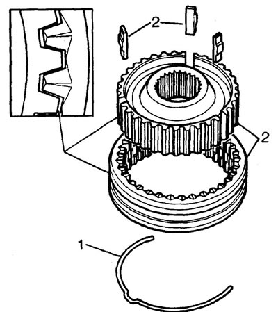
3. Check the condition of all parts, including the elasticity of the spring half rings.
4. Check that there is no noticeable radial clearance between the splines of the synchronizer hub and the secondary shaft.
5. Check the radial splines of the clutch and synchronizer hub for wear.
6. Check the synchronizer axial splines and gears for wear.
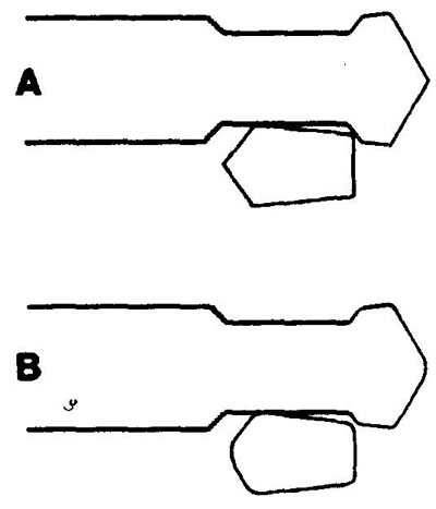
Note: The figure shows examples of the shape of the axial splines. A - normal condition, B - worn spline (rounded corners).
7. If there is wear, replace the synchronizer assembly.
Assembly
1. Install the coupling onto the hub.
Note: The coupling and hub are installed in only one position along the master spline. Couplings are identified by semicircular marks applied to the gear side. The slot in the hub must be aligned with the center mark on the coupling.
| synchronizer | hub | coupling | broadcast |
| 1/2 gear | — | 1 tag | first |
| On two gears | — | second | |
| 3/4 gear | — | 3 tags | third |
| — | — | fourth | |
| 5/reverse | — | 5 tags | fifth |
2. Install crackers and spring half rings. The locks of the half rings must be located in different crackers.
Note: the 5th gear/reverse synchronizer has spring half rings of different design. Identification by yellow color mark.
Checking the clearance between the locking ring and the gear
1. Press the synchronizer locking ring against the gear and measure the gap between them. Minimum gap 0.5 mm.
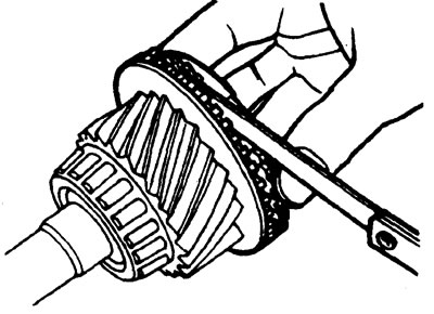
Primary shaft - repair
1. Check the condition of the gear teeth and axial splines.
2. Using mandrels LRT-99-004 and LRT-37-004, remove the secondary shaft support bearing race.
Note: The LRT-37-004 mandrel grip must support the bearing.
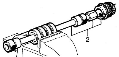
3. Using the LRT-37-001 mandrels and the LRT-99-002 puller, remove the tapered roller bearing.
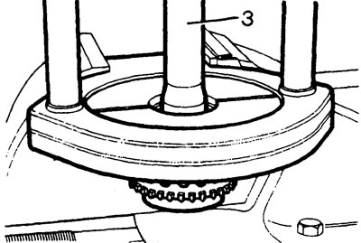
4. Press on the raceway of the new secondary shaft support bearing. Shaft stop in puller LRT-99-002.
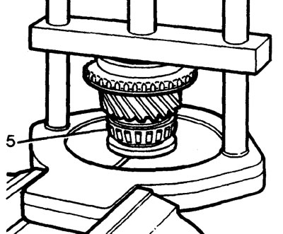
5. Using the LRT-37-001 mandrel, LRT-99-002 puller and LRT-37-002 adapter, install the new roller bearing.
Secondary shaft - check
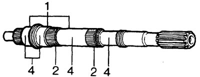
1. Check the condition of the shaft journals for installing bearings.
2. Check the condition of the splines.
3. Blow out the central channel of the shaft for oil supply with compressed air
4. Blow out the radial oil supply channels.
Intermediate shaft - repair
1. Using the LRT-37-022 mandrel and the LRT-99-002 puller, remove the intermediate shaft bearings.
2. Check the shaft for wear or damage.
Note: The main case intermediate shaft and 5th gear intermediate shaft on later model transmissions are machined so that the installation of a lock washer prevents the gear from moving on the shaft. If necessary, such a kit can be installed on the gearbox of early models.
3. Using the LRT-99-002 puller and thrust blocks, install new bearings.
Secondary shaft - assembly
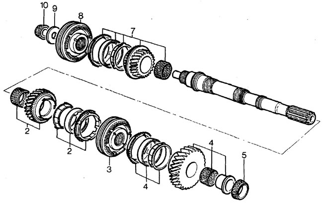
1. Clamp the secondary shaft in a vice with the output end facing up.
2. Install the 2nd gear needle bearing, 2nd gear and synchronizer rings (rotate the rings for a secure fit).
3. Install the 1/2 gear synchronizer (mark to the 2nd gear). Check that the locking ring fits correctly into the synchronizer hub, (when installing the hub, slightly rotate the ring).
4. Install the 1st gear locking rings, needle bearing, 1st gear gear and sleeve. Check that the locking ring fits correctly into the synchronizer hub.
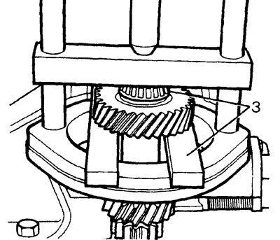
5. Using tools LRT-99-002, LRT-37-019, LRT-37-001 and LRT-37-002, press on the tapered bearing. When pressing the bearing, be careful not to displace the synchronizer locking rings from the gears.
6. Using a flat feeler gauge, measure the axial clearance between the 1st and 2nd gears and the bearing.
Permissible clearance
- 1st gear: 0.05 - 0.20 mm
- 2nd gear pinion: 0.04 - 0.21 mm
7. Turn the secondary shaft over. Install the needle bearing, 3rd gear gear and synchronizer rings.
8. Install the 3/4 gear synchronizer (mark to the 3rd gear).
9. Install the spacer.
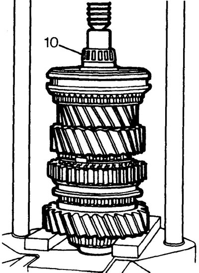
10. Using the LRT-99-002 puller, press on a new support bearing.
11. Check the axial clearance between the 3rd gear pinion and the bearing.
Permissible clearance: 0.11 - 0.21 mm
Reverse idler gear - installation
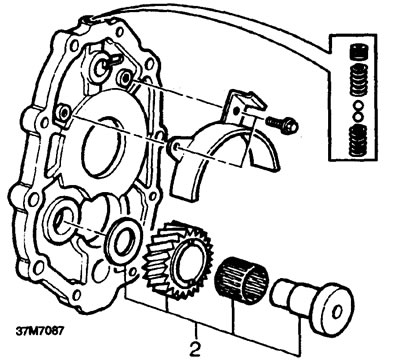
1. Check the condition of the idler gear assembly parts. Replace defective parts.
2. Install the spacer, needle bearing, idler gear and pinion shaft into the intermediate plate. Measure the gap between the gear and the plate.
Permissible clearance: 0.04 - 0.38 mm
Shift forks - inspection
1. Check the rod and pins for wear.
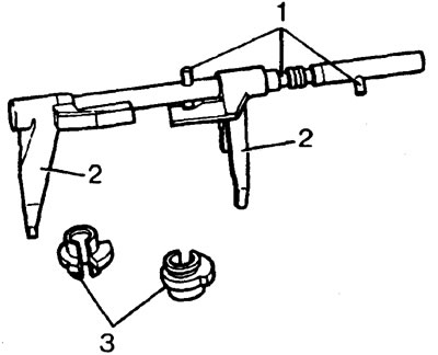
2. Check for wear on the forks.
Note: The shift rod and forks are supplied as an assembly in spare parts.
3. Check the locking bushings for wear.
4. Check the leash for wear.
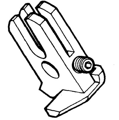
Gearbox type A
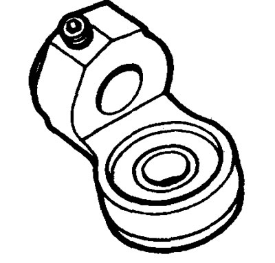
Gearbox type C
5. Remove the retaining ring and check the condition of the leash assembly.
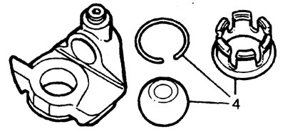
Gearbox type B and D
Shift forks - installation
1. Install the 1/2 gear shift fork onto the rod. Insert the rod pin into the fork notch.
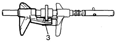
2. Install the locking sleeve and the 3/4 gear shift fork. Engage the sleeve and fork.
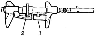
3. Slide the sleeve and fork in the direction of 1/2 gear selection so that the slot in the sleeve is located above the pin that holds the sleeve engaged in the slot in the 3/4 gear fork.
Comments on this article